background image

Electromagnetic flowmeter for volumetric filling 
machines 

BATCHFLUX 5500 C

BATCHFLUX 5500 C

BATCHFLUX 5500 C

BATCHFLUX 5500 C

Quick Start

Quick Start

Quick Start

Quick Start

© KROHNE 05/2014 - 4003386301 - QS BATCHFLUX 5500 R03 en

Summary of Contents for BATCHFLUX 5500 C

Page 1: ...etic flowmeter for volumetric filling machines BATCHFLUX 5500 C BATCHFLUX 5500 C BATCHFLUX 5500 C BATCHFLUX 5500 C Quick Start Quick Start Quick Start Quick Start KROHNE 05 2014 4003386301 QS BATCHFLUX 5500 R03 en ...

Page 2: ...8 2 7 1 Inlet and outlet 8 2 7 2 Control valve 8 2 7 3 Pump 8 2 7 4 Open feed or discharge 9 2 7 5 Mounting 9 2 7 6 Mounting position 9 2 7 7 Installation location 10 2 7 8 Flange deviation 10 2 7 9 Temperatures 11 2 7 10 Hot filling 11 3 Electrical connections 12 3 1 Safety instructions 12 3 2 Grounding 12 3 3 Electrical connection 13 3 3 1 Cable connector M12 5 pin 13 3 3 2 Cable connector M12 8...

Page 3: ...ctions can result in damage to the device or to parts of the operator s plant INFORMATION These instructions contain important information for the handling of the device CAUTION Installation assembly start up and maintenance may only be performed by appropriately trained personnel The regional occupational health and safety directives must always be observed LEGAL NOTICE The responsibility as to t...

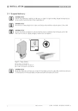
Page 4: ... that you have all the elements given in the order INFORMATION Look at the device nameplate to ensure that the device is delivered according to your order Check for the correct supply voltage printed on the nameplate Figure 2 1 Scope of delivery 1 Flowmeter in ordered size 2 Product documentation on request 3 CD ROM with product documentation INFORMATION Assembly materials and tools are not part o...

Page 5: ...housing in size DN2 5 6 Version 2 converter and sensor in solid cast BNG construction for DN10 and DN 15 Version 3 converter mounted on conventional sensor construction DN25 and DN40 2 3 Nameplate Figure 2 2 Device version 1 DN2 5 4 6 1 10 1 6 1 4 2 DN10 DN15 3 8 1 2 3 DN25 DN40 1 11 2 Figure 2 3 Nameplate 1 Name and address of the manufacturer 2 Type designation S N nr and year of manufacturing 3...

Page 6: ...before starting installation O ring L ring gasket Special pipe flanges Stud bolt with lockwasher plain washer and nut 2 6 General requirements INFORMATION To facilitate servicing and or exchanging of the device please note that it must be possible to shut off the flow through the pipeline control valve upstream in pipeline Drain the pipeline before removing device provide drain valve INFORMATION T...

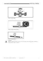
Page 7: ...386301 QS BATCHFLUX 5500 R03 en Figure 2 4 Avoid vibrations Figure 2 5 Avoid strong magnetic fileds Figure 2 6 Horizontal piperun CAUTION Install in a slightly descending pipe section to prevent air from collecting and to avoid faulty measurements meter can drain ...

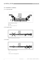
Page 8: ...R03 en 2 7 Installation conditions 2 7 1 Inlet and outlet 2 7 2 Control valve 2 7 3 Pump α 2 1 Drain valve to empty pipeline Figure 2 7 Inlet and outlet section 1 5 DN 2 2 DN 3 Drain valve to empty pipeline 3 Figure 2 8 Installation before control valve Figure 2 9 Installation after pump ...

Page 9: ...or discharge 2 7 5 Mounting 2 7 6 Mounting position α 2 1 Drain valve to empty pipeline Figure 2 10 Installation before an open discharge Figure 2 11 Installation in bending pipes CAUTION Avoid draining or partial filling of the flow sensor WARNING Vertical down position only in conjunction of a control valve ...

Page 10: ...ation 2 7 8 Flange deviation Figure 2 12 Installation location CAUTION Mount the flow sensor in such a way that the electrode axis X X is approximately in a horizontal pipe run Figure 2 13 Mounting position and flange deviation 1 Lmax 2 Lmin CAUTION Max permissible deviation of pipe flange faces Lmax Lmin 0 5 mm 0 02 ...

Page 11: ...e 2 Process temperature Installation position Figure 2 14 In case of hot fluids INFORMATION Avoid installation near hot product tanks If possible try to insulate the flowmeter from radiant heat sources CAUTION On high temperature pipes and where temperatures exceed 100 C provide facilities to compensate for longditudinal expansion of pipeline due to heat up Use flexible pipe elements e g elbows ...

Page 12: ...ING Observe without fail the local occupational health and safety regulations Any work done on the electrical components of the measuring device may only be carried out by properly trained specialists INFORMATION Look at the device nameplate to ensure that the device is delivered according to your order Check for the correct supply voltage printed on the nameplate CAUTION The grounding wire should...

Page 13: ...n plus operation software can be used Use one of the following attachment plug types to connect the flowmeter to a third party system moulded plug straight or angle entry form integrally extruded plug with cable in various lengths moulded plug straight form especially suitable for high interference environments Possible vendors of these plugs are Binder Hirschmann Lumberg Amphenol Coninvers 1 24 V...

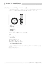
Page 14: ... or an error signal Options on status output 7 Off Error Flow direction Mode Status output On Off Flow direction Default value Flow Direction Forward flow status output open Reversed flow status output closed Error software application failure Error signaling for following events software failure or application failure detection of empty pipe only No error status output open 1 24 VDC 2 Not Connect...

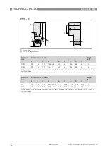
Page 15: ...1 128 54 1 6 DN6 50 156 206 9 4 8 44 88 141 128 54 1 6 Note on dimension d As the diameter reduces to the middle the diameter is specified for the inlet and for the middle Nominal size Dimensions inches Weight lb a b c d e f g h i 1 10 1 97 6 14 8 11 0 24 0 10 1 73 3 46 5 55 5 0 2 13 3 4 1 6 1 97 6 14 8 11 0 28 0 13 1 73 3 46 5 55 5 0 2 13 3 6 1 4 1 97 6 14 8 11 0 35 0 19 1 73 3 46 5 55 5 0 2 13 3...

Page 16: ...50 140 179 14 12 45 4 60 106 5 88 54 1 4 Note on dimension d As the diameter reduces to the middle the diameter is specified for the inlet and for the middle Nominal size Dimensions inches Weight lb a b c d e f g h i 3 8 1 97 5 51 7 05 0 41 0 31 1 79 2 36 4 19 3 46 2 13 3 1 1 2 1 97 5 51 7 05 0 55 0 47 1 79 2 36 4 19 3 46 2 13 3 1 Note on dimension d As the diameter reduces to the middle the diame...

Page 17: ...8 1 6 DN40 50 177 219 39 30 84 117 141 128 83 2 3 Note on dimension d As the diameter reduces to the middle the diameter is specified for the inlet and for the middle Nominal size Dimensions inches Weight lb a b c d e f g h i 1 1 97 6 69 8 03 1 02 0 79 2 68 4 02 5 55 5 04 2 28 3 6 1 1 2 1 97 6 97 8 62 1 54 1 18 3 30 4 61 5 55 5 04 3 27 5 1 Note on dimension d As the diameter reduces to the middle ...

Page 18: ... Flange 3 25 Ø 25 Ø 31 3 Ø 41 2 Ø 49 2 15 47 3 53 Size DN a1 mm a2 mm b mm c mm 2 5 Ø 10 Ø 6 2 Ø 11 1 Ø 18 4 4 Ø 10 Ø 7 2 Ø 12 1 Ø 19 4 6 Ø 10 Ø 9 2 Ø 14 2 Ø 21 5 10 Ø 10 Ø 10 7 Ø 15 7 Ø 23 INFORMATION The O rings require periodic inspection and replacement As the interval depends on process specific variables the length of the interval cannot be specified The O rings are not part of the portfolio...

Page 19: ...DN40 on request Size DN Pcd mm D mm W mm Drawing number 2 5 Ø 56 Ø 68 14 5 4000587801 4 Ø 56 Ø 68 14 5 4000587807 6 Ø 56 Ø 68 14 5 4000587810 10 Ø 56 Ø 68 14 5 4000587815 15 Ø 56 Ø 68 14 9 4000587818 25 Ø 84 Ø 104 16 5 4000587824 40 INFORMATION Detailed construction drawings of the above sketches are available from the download centre see table for drawing numbers ...

Page 20: ...Analysis products Products and systems for the oil gas industry Measuring systems for the marine industry Head Office KROHNE Messtechnik GmbH Ludwig Krohne Str 5 47058 Duisburg Germany Tel 49 203 301 0 Fax 49 203 301 103 89 info krohne com KROHNE 05 2014 4003386301 QS BATCHFLUX 5500 R03 en Subject to change without notice The current list of all KROHNE contacts and addresses can be found at www kr...

Reviews: