18
5 6 4 4.1 4.2 11 12
}
Output
Connections
see Section 3.3
PE
N L AC
- + DC
}
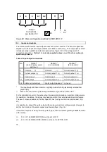
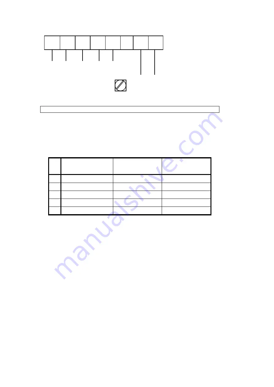
Figure 22: Power and signal connections for MFC 081 K / F
3.3
Inputs and outputs
The table below shows the input/output connection for the converter. The exact configuration
depends on which optional output modules were fitted in the factory. The output options listed
include presently available and planned options. See Figure 22 for the arrangement of
converter connections. Option 1 is normally supplied unless one of the other options is
specifically ordered.
Table of input/output connections
No.
Option 1
(Current, pulse, alarm
and input )
Option 2
*
(2 current,NGI)
Option 3
**
(2 current,GI)
5
Common (-)
Common (-)
Current output 1 (-)
6
Current output (+)
Current output 1 (+)
Current output 1 (+)
4
Control input
Control input.
Current output2 (-)
4.1
Pulse output
Current output 2 (+)
Current output 2 (+)
4.2
Alarm output (active)
Alarm output (passive)
not used
*
The inputs/outputs share a common signal ground which is galvanically isolated from
ground (PE).
**
Both current outputs are galvanically isolated from ground and each other.
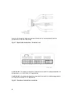
For the standard converter, the pulse output is passive and requires an external voltage source
for operation. In addition, the signal may need protection from external electrical interference.
The use of screened cables and a filter capacitor next to any counter is recommended. (Fig.
23)
It is possible to connect the pulse output without using an external voltage supply. However to
do this the function of the alarm output must be sacrificed. (Fig. 24).
If the alarm output is used to power the pulse signal, then the following settings must be made
in the menus.
(i)
Fct. 3.5.1 ALARM FUNCTION must be set to OFF
(ii)
Fct. 3.5.2 ALARM ACTIVE LEVEL must be set to ACTIVE LOW.


