92
9.8
Checking the Primary Head
Remember! Always switch the power off before opening the converter housing.
If application and installation criteria have been carefully reviewed and the converter
electronics is deemed not at fault, the following checks can be performed on the primary head.
Whether the system has a remote or compact converter, it is most convenient to first remove
the 10 pin sensor connector (C) from the converter as outlined below to isolate the converter
electronics.
For compact systems, remove the rectangular cover to the connection compartment mounted
to the primary head. Note, one of the four screws can only be loosened so the cover can be
rotated out of the way around this screw. Using an appropriate ohmmeter, check the
resistance between the various terminals according to the wire colors described on the next
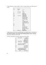
page. Color/terminal identification can be seen in Section 4.8, Fig. 32. The pin out for the
various wire colors for the converter connector is shown below should the cable need to be
checked.
For remote mounted converters, the same procedure can be followed as for the compact
systems by checking at the converter connection compartment first. If a problem is found, a
similar test should be performed at the primary head (transducer) connection compartment to
check out the connecting cable and its connections. Refer to the cable connection diagrams in
Section 4.7.
Required tools and test equipment
–
Phillips screwdriver
–
Multimeter
–
Special wrench to unscrew converter housing lids
A. Screws that hold the display
PCB in place.
B. Ribbon cable connecting
display PCB to converter
electronics.
C. 10-pin sensor connector.
D. Screws that hold the converter
electronics in place.
P. Power supply circuit board
Preliminary preparation
–
Remove front lid of electronic housing
–
Unscrew the two screws “A” that hold down the display PCB and fold the ribbon cable and
PCB carefully to one side.
–
Unplug blue primary connector “C” from amplifier board
B
C
P


