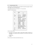
background image

49


For systems with concentration software their specific extra displays will be added to the above
list from Fct. 1.2.9 onwards.


The displayed measurement function can be changed in the measurement mode by pressing 

key.


The setting of the display output is demonstrated for the example of displaying the mass flow
rate in kg/h.


Starting from the display of measurement values, the following programming steps are
necessary.


Begin from measuring mode.


After pressing 

 key the display shows :


0000.0000 (kg)/min


This display means that mass flow will be displayed in units of kg/min to an accuracy of 4
decimal places.


The brackets around 'kg' indicate the cursor position, these characters will be flashing on the
display. The flashing value can now be changed with the 

 key. By pressing the 

 key the

cursor moves to 'min' which starts to flash.


This dimension may now also be changed by using the 

 key. After pressing the 

 key again,

the cursor moves to the output format of the numeric value which can then be edited.


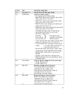
To change the display to kg/h with 5 decimal places, follow the following procedure.


Key

Display


line 1

line2


Fct. (1).0

OPERATOR


2x

Fct. (3).0.

INSTALL


Fct. 3.(1).0.

BASE DATA


Fct. 3.(2).0.

DISPLAY


→↑↑

Fct. 3.2.(3).

MASS FLOW


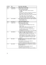
Key

Display


line 1

line 2


0000.0000

(kg)/min


0000.0000

kg/(min)


0000.0000

kg/(h)


0000(.)0000

kg/h


00000(.)000

kg/h


000000(.)00

kg/h


0000000(.)0

kg/h


00000000(.)

kg/h


0(.)0000000

kg/h


00(.)000000

kg/h


000(.)00000

kg/h


Fct. 3.2.(3).


MASS FLOW


Summary of Contents for CORIMASS MFM 4085 K/F

Page 1: ...02 98 CORIMASS G Class Single straight tube mass flow meter Installation and Operating Instructions MFM 4085 K F...

Page 2: ...are applicable which are specified in the special Ex installation and operating instructions supplied only with hazardous duty equipment Responsibility as to suitability and intended use of our instr...

Page 3: ...3 2 Initial start up 22 3 3 Installation factor 22 3 4 Zero point adjustment 22 3 5 Programming the converter with a bar magnet 24 Part B MFC 085 Signal Converter 25 75 4 Operation of the Signal Conve...

Page 4: ...7 1 4 Testing alarm output 80 7 1 5 Testing control input 80 7 1 6 Viewing temperature and strain 81 7 1 7 Viewing primary head signal conditions 81 8 Service and Troubleshooting 82 8 1 Threads and O...

Page 5: ...he CORIMASS is an active device with its own energy source A good installation is essential for the high measurement accuracy The following installation guidelines are practical to implement particula...

Page 6: ...ength of the meter Figure 3 Avoid mounting the meter at the highest point in the pipeline Air or gas can accumulate here and cause faulty measurements Figure 4 The use of reducers at the flanges is al...

Page 7: ...ry clamps may be required Figure 6 Note See table on next page for information on supports for distances L To enable a good zero to be done it is recommended that a shut off valve be installed downstr...

Page 8: ...meter should fit between the connecting pipe with perhaps 2 3 mm 1 8 inch to spare It should not be necessary to force the pipes apart to fit meter Flanges should be correctly aligned Tighten flange...

Page 9: ...llowing procedure to check the installation factor Warm up the electronics for at least 30 minutes Flush the meter with water or product to ensure that all trapped air has been removed Key Display Lin...

Page 10: ...anges up to the 300 G The 800 G 1500 and 3000 G has a different requirement due to the weight of the meter The standard sanitary connectors are not capable of carrying the weight of the meter As a saf...

Page 11: ...not generally necessary or desirable to heat or insulate the case of the meter This is because the central measuring tube is not thermally coupled to the case except at the extreme ends It is then onl...

Page 12: ...be firmly fixed to the meter with no components such as straps or covers that can vibrate figure 11 DO NOT insulate converter figure 12 Figure 11 Important Note When insulating Ex meters insulation m...

Page 13: ...pipework if this is done it should be firmly fixed with no loose wires or connections that could vibrate If only pipework and flanges are insulated two turns of heating tape should be tightly applied...

Page 14: ...s small a diameter as possible and the wall thickness should be as thin as possible figure 18 A radial gap between the process pipe and the inside of the jacket of 5 6mm is suitable The minimum clampi...

Page 15: ...speed this up if the meter is mounted vertically and a reduction of about an hour is possible if the case is insulated If the case is also heated heating times are further cut The above comments assum...

Page 16: ...refer to Krohne Ltd This does not apply to the 3000G These meters must not exceed 130 C Zirconium tube meters must never exceed 100 C ALLOWABLE TIME AT HIGH TEMP 10 G METER 0 10 20 30 40 50 60 70 80 9...

Page 17: ...r to direct sunlight Install a sunshade if necessary Connecting cables To conform to protection category requirements observe the following recommendations Fit blanking plug PG 16 and apply sealant to...

Page 18: ...osive to aluminium typically it must be resin and acid free Protect sealing ring from damage Outputs and connections see Sect 2 3 Power and signal connections for MFC 085 K 2 3 Inputs and outputs The...

Page 19: ...ever to do this the function of the alarm output must be sacrificed Fig b If the alarm output is used to power the pulse signal then the following settings must be made in the menus i Fct 3 5 1 ALARM...

Page 20: ...nt output 2 4 1 TX RX TX RX Pulse Output A Control Input Current output 3 Current output 3 Current output 3 4 2 5V 5V Pulse Output B Pulse Output Pulse output Control Input status output passive The p...

Page 21: ...w meter is programmed to a standard default set of values and functions The current and pulse outputs treat all flows as positive The actual flow and quantity is thereby measured independent of the fl...

Page 22: ...keystroke combination as in Sect 1 2 3 If correctly installed the value of the installation factor when the primary head is full of water should be as per table in section 1 2 3 If the figure is high...

Page 23: ...In such cases the zero point adjustment procedure is automatically aborted and the following message is displayed for a short time ZERO ERROR Then the converter returns to the start of the function 1...

Page 24: ...eans of the magnetic sensors mounted on the faceplate without removing the front lid To do this a bar magnet standard supply is used to activate the sensors by holding the magnet close to the glass wi...

Page 25: ...nd functions can be set in this menu Parameter check level Fct 4 0 PARAM ERROR This level is not selectable After exiting from the Setting level the signal converter checks new data for plausibility I...

Page 26: ...26 4 2 Krohne Operating Concept...

Page 27: ...nges to Fct 1 1 0 Text Change text field i e YES to NO or g to kg to t etc Sign Toggle to Cursor or Right Key This key moves the cursor onto the next field to be edited usually the next on the right N...

Page 28: ...Fct 1 0 OPERATOR Press 1 3 times until the cursor is under the extreme left menu column Fct 1 0 2 0 or 3 0 12 345 kg min or If no changes have been made to the system s configu ration return directly...

Page 29: ...are displayed Fct 1 0 OPERATION Fct 2 0 TEST or Fct 3 0 INSTALL Press key F c t 3 0 I N S T A L L A C C E P T Y E S To accept the new parameters Press to confirm PARAM CHECK will appear in the display...

Page 30: ...6 0 k g m i n k g m i n To change the text Select next text M A S S F L O W D E N S I T Y To change the units Numeric values automatically converted Select new unit 0 2 1 0 6 0 2 1 0 6 0 g m i n k g m...

Page 31: ...VOLUME FLOW Unit for volume flow See Fct 3 2 7 1 2 8 VOLUME TOTAL Unit for volume total See Fct 3 2 8 1 2 9 CONC MEAS Parameters for concentration measurement See separate concentration measurement in...

Page 32: ...es of the required width To stop the test press twice 2 4 TEST A Test alarm output SURE NO Use the key to select YES then press LEVEL LOW 0 Volts is output on the alarm terminal Press the key to switc...

Page 33: ...BY Use the key to switch between three modes of operation then press MEASURE STANDBY tube vibrating Mass Flow set to zero STOP tube drive stopped Note It is not possible to switch directly from STOP t...

Page 34: ...mass flow display g kg t oz lb per s min h d Number of digits after the decimal point selectable 3 2 4 MASS TOTAL Units and format for totaliser g kg t oz lb Number of digits after the decimal point...

Page 35: ...ons available if installed CONC BY see sep instruction manual DIRECTION Negative flow gives current of 0 4 mA positive flow gives current of 20 mA 3 3 2 RANGE I Range for current output I Select from...

Page 36: ...oncentration parameters if CONC BY MASS option installed See separate CON BY VOLUME instruction manual DIRECTION Negative flow gives output of 0 volts DC Positive flow gives output of V volts DC 3 4 2...

Page 37: ...as set in Fct 3 3 3 and 3 3 4 P 1 SAT Alarm active if value output on pulse output is either 1 3 x Max Limit as set in Fct 3 3 4 or Min Limit as set in Fct 3 3 3 ANY O P SAT Alarm active if value out...

Page 38: ...FLOW 0 RST Mass flow readings forced to zero totaliser frozen while active but reset to zero as condition becomes inactive Not available with Custody Transfer Protection OUTPUTS OFF Forces all output...

Page 39: ...r HHC connected to current output Factory setting MFC 085 Characters assignable to each place A Z 0 9 blank character 3 8 5 ENABL RESET Allow totaliser reset from the RESET ACKNOWLEDGE menu or with Co...

Page 40: ...entioned on the cal Sheet 3 9 8 FSS CF8 Slope strain Displays the value which is mentioned on the cal Sheet 3 9 9 FTS CF9 Slope temperature Displays the value which is mentioned on the cal Sheet 3 9 1...

Page 41: ...IN LIMIT Minimum limit for range checking see Fct 3 5 3 4 7 2 MAX LIMIT Maximum limit for range checking see Fct 3 5 4 4 8 0 SYS CTRL S Minimum and maximum limits incorrect MIN LIMIT 96 of MAX LIMIT 4...

Page 42: ...MASS FLOW The symbols indicate that this is a new error and not one that has been previously acknowledged Use either the or keys to view other messages in the list Otherwise press to exit 1 Err QUIT Y...

Page 43: ...mber of write cycles MASS FLOW Light Mass flow rate 2 nominal flow ZERO ERROR Light Mass flow rate at zero adjust is larger than 20 of nominal 100 flow rate TEMPERATUR Light Temperature outside operat...
Page 44: ...TEST INP E BLOCKED BLOCKED BLOCKED BLOCKED BLOCKED TEST INP E BLOCKED Fct 3 3 CUR OUTP I CUR OUTP I CUR OUTP I CUR OUTP I CUR OUTP I CUR OUTP I CUR OUTP I CUR OUTP I CUR OUTP I Fct 3 4 PULS OUTP P BL...

Page 45: ...inutes prior to starting the adjustment After flushing flow in the primary head must be brought back to zero by tightly closing appropriate valves The zero off set can either be measured automatically...

Page 46: ...perly There are still gaseous inclusions in the primary head because it was flushed insufficiently Resonant vibration of the piping interferes with the primary head because of poor clamping In such ca...

Page 47: ...e way flow is selected this averaging process will not work and the totaliser reading will increase slowly with time To prevent this the Low Flow Cutoff should be set The Low Flow Cutoff is entered as...

Page 48: ...conds is available as a factory set option Time constant characteristic 5 4 Programming the display for measurement values Fct 1 2 and 3 2 The following measurement functions can be displayed Key Disp...

Page 49: ...The brackets around kg indicate the cursor position these characters will be flashing on the display The flashing value can now be changed with the key By pressing the key the cursor moves to min whi...

Page 50: ...a cyclic display of all measurement values is desired the following inputs have to be added to the previous steps With the cyclic display enabled the converter will switch displays in the measuring mo...

Page 51: ...ple If no extra digits are required pressing the key will cause this leading zero to be blanked 0 5 0000 kg min 5 0000 Some values do not allow the decimal point to be moved Key Display line 1 line 2...

Page 52: ...4 to 20 mA warning state 3 5 mA All output ranges will over range to 20 5 mA The 4 20 mA ranges will under range to 3 8 mA All functions except flow direction have a minimum and a maximum value When t...

Page 53: ...mits the output is said to be saturated This may cause problems with external instrumentation Saturation may be indicated to the customer using either the process alarm section 5 7 or the status warni...

Page 54: ...54 Current output characteristics...

Page 55: ...the Concentration option the following functions are also available VALUE OUTPUT TYPE Concentration by mass Brix Frequency Concentration by volume Frequency Solute flow Brix rate Frequency Solute Tota...

Page 56: ...ould take into account the maximum flow rate Flowmax he expects through the meter such that Flowmax Q 2 where Flowmax is in units g s or cm 3 s Q is in units of g or cm 3 is in units of seconds If Flo...

Page 57: ...of process fluid going through the primary head NOTE The pulse output ignores the sign positive or negative of the flow To ensure reliable operation the system should be set for one way flow with suit...

Page 58: ...maximum output frequency is 1300 Hz so the Max Value allowed for Fct 3 4 2 is 1000 Hz allowing for the 1 3 x over range NOTE The frequency output has a duty cycle of 50 for a frequency range 1Hz For a...

Page 59: ...he maximum limit the output switches to active However as flow then decreases the output will not switch to inactive until it becomes less than MAX H where H 2 of upper limit Process alarm functions F...

Page 60: ...e Begin from measuring mode Return to measuring mode NOTE For functions other than range checking Fct 3 5 3 and 3 5 4 are not accessible Key Display line 1 line 2 Fct 3 0 INSTALL 4x Fct 3 5 0 ALARM OU...

Page 61: ...on the transition of the input from inactive to active The active level of the input may be defined using Fct 3 6 2 as active high 4 24 volts or active low 0 2 volts NOTE Internal resistors attached...

Page 62: ...same way as the process alarm see Sect 5 7 When such a condition is met the converter takes one of the following actions 1 Flow reading forced to zero totaliser stopped any output registering flow wi...

Page 63: ...zero and will be displayed as shown below 0 0000 STANDBY 5 11 Standby function Fct 1 1 4 and 3 1 4 The instrument may be switched to a STANDBY state Once in this state all outputs go to their off stat...

Page 64: ...mode If STANDBY or STOP was selected the instrument goes immediately into that state To return to measurement go back to Fct 1 1 4 and select MEASURE NOTE It is not possible to change mode directly f...

Page 65: ...er must be dry inside with no droplets of liquid If necessary blow through with clean compressed air to dry If a fluid is used circulate the fluid at a high flow rate for a few minutes to ensure that...

Page 66: ...means that the meter was unable to calculate realistic values for CF1 and CF2 Press to continue This error may be caused by a number of factors Please check the following Check initial values of CF1 a...

Page 67: ...ensity input by the customer will be displayed If required these values can be edited here Note if the value is edited CF1 and CF2 will be adjusted Fct 3 9 10 D REF HIGH Fct 3 9 11 D REF LOW Repeat fo...

Page 68: ...40535 36 98 6 993 6948 62 03637 11 5 52 7 999 5529 62 40209 36 5 97 7 993 5187 62 02537 12 53 6 999 4975 62 39863 37 98 6 993 3406 62 01426 12 5 54 5 999 4389 62 39497 37 5 99 5 993 1606 62 00302 13...

Page 69: ...36 4 984 3086 61 45039 73 5 164 3 976 0076 60 93216 58 5 137 3 984 0604 61 43489 74 165 2 975 7204 60 91423 59 138 2 983 8108 61 41931 74 5 166 1 975 4321 60 89623 59 5 139 1 983 5597 61 40364 75 167...

Page 70: ...ship of the process over the range of operating temperatures Also note that the coefficient depends on the temperature units selected F or C as well as the density units selected The units of are the...

Page 71: ...ing mode 5 14 2 Password protection of menus As mentioned in Section 4 2 access to the menus can be protected by a password This password protection is enabled by Menu 3 8 2 and the password itself ca...

Page 72: ...tered Primary head type and CF 1 to 5 Low flow cut off Custody transfer password Mass total display units and format Flow direction Flow mode Set to FLOW 0 only Standby Control input function Only ack...

Page 73: ...character code is displayed With this character code the manufacturer can decode the password in cases where the password is lost It is also possible to protect just the mass totaliser Menu 3 8 5 ENAB...

Page 74: ...t PARAM CODE 4 password Fct 1 0 OPERATION Fct 3 0 INSTALL 7 Fct 3 8 0 USER DATA 7 Fct 3 8 8 PARAM CODE 4 CodE 4 OK Fct 3 8 8 PARAM CODE 4 The operator may now edit if required CF3 CF4 CF5 as well as P...

Page 75: ...is being used To set the location number Begin from measuring mode Use the key to change the character under the cursor The sequence is A to Z 0 to 9 SPACE Use the key to move the cursor to the next c...

Page 76: ...ied personnel Most of these options are hi pot tested to comply with the requirements of Ex and CE and if field exchanged these requirements may be violated Krohne will also not accept responsibility...

Page 77: ...ns a number of test functions These allow the current frequency and alarm outputs to be driven at a number of fixed test levels so that the communication between the converter and the customer s equip...

Page 78: ...sired output number Fct 3 3 0 CUR OUT I Fct 3 3 0 CUR OUT I 1 Fct 3 3 0 CUR OUT I 2 Use the key to select the desired output number Fct 3 3 1 FUNCTION I Program the selected output as normal 7 1 3 Tes...

Page 79: ...ect a pulse counter to the impulse output and proceed as follows Fct 2 3 0 TEST P SURE NO SURE YES Fct 2 3 1 FREQUENCY Fct 2 3 2 TEST PULSE 0 4 mSec Use the to select the desired pulse width 1 0 mSec...

Page 80: ...reads a larger number than the converter or if the frequency meter reading is high or unstable then this indicates the presence of external interference Try one or more of the following i Add increase...

Page 81: ...an this it indicates that the vibrations of the primary head are being impeded This could be due to a poor installation or a large quantity of air in the process fluid Frequency menu 2 7 3 This functi...

Page 82: ...ench to remove the cover from the electronic compartment 4 Undo screws A and fold display board to side 5 Remove plug C 10 pin signal cable 6 Undo screws D using a screwdriver for recessed head screws...

Page 83: ...osition of fuses see power supply board layout diagram Voltage Fuse F9 200 230 240 VAC 160 mA T 100 115 120 VAC 315 mA T 42 48 VAC 800 mA T 21 24 VAC 1 6 A T The fuses should be in anti surge type wit...

Page 84: ...g and operating elements on MFM 4085 K compact flow meters that are installed in locations that are hard to get at the signal converter housing can be turned through 90 1 The connection wires between...

Page 85: ...mary head s INSTAL FACT using Fct 2 7 4 If the reading is high see Section 1 2 3 then this indicates either poor meter clamping or excessive gas in the process fluid For horizontally installed systems...

Page 86: ...ashing showing that all the problems detected so far have been acknowledged However the status arrow will only be extinguished if there are no longer any messages present in the list It is also possib...

Page 87: ...write cycles MASS FLOW Light Mass flow rate 2 nominal flow ZERO ERROR Light Mass flow rate at zero adjust is larger than 20 of nominal 100 flow rate TEMPERATUR Light Temperature outside operating ran...

Page 88: ...s Time constant too small Increase time constant as per Section 5 3 D3 Mass flow display incorrect The wrong values for parameters CF3 CF5 programmed These are stamped on the data plate Check and corr...

Page 89: ...resent If still faulty the alarm or pulse output is faulty Re place converter or call Krohne Service Pulse output is switched off Switch on as per Fct 3 4 1 P2 Fluctuating pulse rate Time constant too...

Page 90: ...and acknow ledge the error message Primary Sensor faulty Check as per Sect 8 8 Fuse F11 blown negative analog voltage Call Krohne Service ST3 Display returns to Start up and the primary sensor is nois...

Page 91: ...o one side Unplug blue primary connector C from amplifier board 10 Pin Sensor Connector C Connector between primary and converter grey white blue green violet black brown orange yellow red Colours in...

Page 92: ...an be done at the terminals On the cast version measurements can be done on the blue primary connector see section 8 8 1 Testing the resistance values of the sensors and exciter Typical values Assesme...

Page 93: ...detect that a measured value is out of range then this also generates an output warning SEVERE These include any fault that causes the primary head to stop vibrating This may be due to large quantitie...

Page 94: ...MARY HEAD Light warnings registered in main display Output warnings ignored OUTPUT Only output warnings in main display ALL MESG All warning messages displayed NOTE Only if OUTPUT or ALL MESGS are sel...

Page 95: ...witching capacity 800 mA T 5 08085 00 1500 A 1 6 A T 5 07823 00 1 25 A T 5 09080 00 TR 5 switching capacity 35 A Fuse Value F 10 5 V Analog voltage 500 mA T F 11 Negative Analog voltage 100 mA T F 12...

Page 96: ...n 25 kg min 50 kg min 15 kg h 120 kg h 300 kg h 900 kg h 1500 kg h 3000 kg h 0 55 lb min 4 4 lb min 11 lb min 33 lb min 55 lb min 110 lb min Measuring accuracy error limits See reference conditions be...

Page 97: ...0 7 0 5 0 7 0 3 Ambient temperature complete flow in operation Standard 30 to 60 C or 20 to 140 F Hazardous duty 20 to 55 C or 4 to 131 F in storage 50 to 85 C or 58 to 185 F Secondary containment ho...

Page 98: ...anically isolated only from mains CPU etc not from other outputs Current 0 20 mA or 4 20 mA Load 500 ohms Linearity 0 2 of measured value in range of 2 20 mA 0 02 of full scale deflection in range of...

Page 99: ...Outputs 1 0 0 0 1 1 0 0 0 Status Outputs 1 1 passive 0 0 0 0 0 1 passive 0 Binary Inputs 1 1 0 0 1 0 1 0 0 TERMINALS 4 2 Alarm Alarm 5V 5V Pulse B Pulse Input Alarm 5V 4 1 Pulse Current 2 TX RX TX RX...

Page 100: ...ured value forward reverse or sum totalizer 7 characters each can be set for continuous or cyclic display and status output Meas quantities and units Plain text language see page 89 Measured quantitie...

Page 101: ...101 10 4 Block diagram of Converter MFC 085...

Page 102: ...19 29 656 25 83 843 33 19 1110 43 70 1242 48 90 1630 64 17 c with different connections On request d 90 3 54 102 4 02 102 4 02 142 5 59 170 6 69 274 10 79 e 208 8 19 208 8 19 208 8 19 208 8 19 208 8...

Page 103: ...9 1110 43 70 1242 48 90 1630 64 17 c with different connections On request d 90 3 54 102 4 02 102 4 02 142 5 59 170 6 69 274 10 79 e 208 8 19 208 8 19 208 8 19 208 8 19 208 8 19 208 8 19 Weight in kg...

Page 104: ...olis forces Fc which act upon the two halves of the tube with opposite direction are directly proportional to the mass flow The Coriolis distortion is extremely small and superposed on the fundamental...

Page 105: ...c flammable or water endangering liquids you are kindly requested to check and ensure if necessary by rinsing or neutralising that all cavities in the flow meter are free from such dangerous substance...

Reviews: