background image


15 


Fct. Text 

Description 

and settings


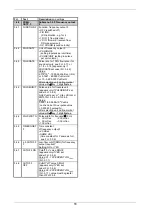
3.3.0 

CUR.OUTP. I  Submenu 3.3.0 Current output I 

3.3.1 FUNCTION 

Function, current output I 

• 

OFF 

(switched off) 

• 

F/R IND.


   (F/R indication, e.g. for F) 

• 

1 DIR.

 (1 flow direction) 

• 

I<I 0 PCT 


(Forward / Reverse flow, 

   e.g. in 0 - 20 mA range: 

   F=10 - 20 mA and R=10 - 0 mA)


• 

2 DIR.

 (Forward/Reverse flow, 

   F/R-measurement) 

• 

SP. SOUND

 (sound velocity) 

3.3.2 

RANGE I 

Range for current output I, see 

Sect. 5.7.2 

• 

0 - 20 mA


• 

4 - 20 mA


• 

OTHER RANGE 


(see Fct. 3.3.3, 3.3.4 + 3.3.5) 

3.3.3 

I 0 PCT. 

Current for 0% flow (I

0%

(appears only if 

OTHER RANGE


set under Fct. 3.3.2). 

Value: 

00

 to 

16 mA


3.3.4 

I 100 PCT. 

Current for 100% flow (I

100%

of full-scale range (Fct. 3.1.1) 

(appears only if 

OTHER RANGE


set under Fct. 3.3.2). 

Value: 

04

 - 

20 mA


(value must be at least 4 mA 

greater than that of Fct. 3.3.4).  

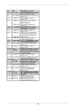
3.3.5 

I MAX mA 

Current limitation (I

max

see Fct. 5.7.2 

(appears only if 

OTHER RANGE

 is 

set under Fct. 3.3.2) 

Value: 

04


20 mA


(value must be at least 4 mA 

greater than that of Fct. 3.3.4). 

3.3.6 TIMECONST.

Time constant of current output I 

Value: 

0.04

 - 

3600 Sec


3.3.7 L.F.CUTOFF 

Low flow cutoff (SMU) for current 

output required? 

Setting: 

NO

 or 

YES


3.3.8 L.F.CUTOFF 

ON 

Cutoff “on” value for SMU-I 

(appears only if YES set 

under Fct. 3.3.7) 

Value: 

01

 - 

19 PERCENT

 of Q

100%


(Fct. 3.1.1) 

3.3.9 L.F.CUTOFF 

OFF 

Cutoff “off” value for SMU-I 

(appears only if YES set 

under Fct. 3.3.7) 

Value: 

02

 - 

20 PERCENT

 of Q

100%


(Fct. 3.1.1),  value must be greater 

than that of Fct. 3.3.8. 


Summary of Contents for GFM 700 F

Page 1: ...asonic flowmeters Mass flowmeters Level measuring instruments Communications technology Engineering systems solutions Switches counters displays and recorders Heat metering Pressure and temperature In...

Page 2: ...upply with protective earthing connected 5 Do not use the product with removed covers under wet conditions 6 Consider handling and lifting instructions to avoid damage 7 Install the product securely a...

Page 3: ...bject to some or all of the above disclamer exclusions or limitations Any product purchased from KROHNE is warranted in accordance with the relevant product documentation and our Terms and Conditions...

Page 4: ...6 Electrical 11 6 1 Electrical connections 11 6 2 Electrical installation to the main supply voltage 11 7 Operation of the signal converter 12 20 7 1 Table of settable functions 12 18 7 2 Error messag...

Page 5: ...low to determine the precise flow velocity for each nominal pipe size Example v in m s Example v in ft s Nominal pipe size DN 150 Required measuring range 1000 m3 h Nominal pipe size 6 Required measur...

Page 6: ...identified by direct measurement of the transit time of ultrasonic waves Assuming the same path length L the transit time in water is shorter than in crude oil for example Propagation rate of ultraso...

Page 7: ...eter DN 50 600 2 24 option DN 700 1200 28 48 Flange connections Pressure rating standard to DIN 2501 DN 50 DN 80 PN 40 40 bar 580 psig DN 65 DN 100 150 PN 16 16 bar 230 psig DN 200 600 PN 10 10 bar 15...

Page 8: ...18 V DC load 680 Ohm Low flow cutoff cutoff on value 1 19 cutoff off value 2 20 of Q100 setting in 1 increments Time constant 0 04 3600 s setting in increments of 1 0 1 or 0 01 s Forward reverse meas...

Page 9: ...ane finish Protection category IP 67 IEC 529 EN 60529 equivalent to NEMA 4 and 4X Signal cable only for remote systems F length up to 10 m 30 ft max 20 m 60 ft option 4 4 Environmental conditions In a...

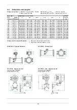
Page 10: ...37 367 14 45 340 13 39 343 13 50 490 19 29 40 88 250 10 10 600 23 62 419 16 50 425 16 73 395 15 55 407 16 02 570 22 44 45 99 300 10 12 700 27 56 470 18 50 489 19 25 445 17 52 483 19 02 610 24 02 55 12...

Page 11: ...Uext 32 V DC 24 V AC I 150 mA EC electronic totalizer EMC electromechanical totalizer 5 Power supply connection and all outputs standard L N L L only internal protective conductor connection terminal...

Page 12: ...required See Fct 3 3 7 1 3 3 CUTOFF ON Cutoff on value SMU I see Fct 3 3 8 1 3 4 CUTOFF OFF Cutoff off value SMU I see Fct 3 3 9 1 4 0 FREQ OUTP F Submenu 1 4 0 Frequency output F 1 4 1 PULSRATE or PU...

Page 13: ...digit flashes 3 1 4 ZERO SET Zero setting FIXED VALUE VALUE MEASU Carry out only at zero flow and with completely filled measuring tube 1 Inquiry CALIB NO or YES 2 if YES calibration duration approx...

Page 14: ...otalizer TOTAL forward and reverse totalizers alternating SUM TOTAL sum of and totalizers ALL TOTAL alternating sum and totalizers TOTAL OFF totalizer switched off 3 2 3 UNIT TOTAL Unit for totalizer...

Page 15: ...low I100 of full scale range Fct 3 1 1 appears only if OTHER RANGE set under Fct 3 3 2 Value 04 20 mA value must be at least 4 mA greater than that of Fct 3 3 4 3 3 5 I MAX mA Current limitation Imax...

Page 16: ...ashes 3 4 3 PULSE UNIT Pulse value for flowrate unit appears only if PULSE UNIT set under Fct 3 4 2 Unit PuLSe per m 3 Liter US Gal or unit of Fct 3 6 6 3 6 7 3 6 8 Value 0 0001 to 9 9999 10 9 PuLSe n...

Page 17: ...urement point no max 10 digits Required only for flowmeters of HHC design operator control via Hand Held Communicator MIC 500 connected to current output Factory setting ALTOMETER Characters assignabl...

Page 18: ...3 6 13 has been reached The corresponding measurement channel will then be made inactive and an indication will be visible on the display Value setting 1 99 PERCENT Factory setting 20 PERCENT 3 5 12 W...

Page 19: ...100 I0 4 mA is met 4 3 1 I 0 PCT Current for 0 flow I0 see Fct 3 3 3 4 3 2 I 100 PCT Current for 100 flow I100 see Fct 3 3 4 4 4 0 I MAXIMUM CURRENT LIMITATION incorrect Ensure condition Imax I100 is...

Page 20: ...ENT of UNIT for F and SOUND VELOCITY 4 9 1 FUNCTION F Function of frequency output F see Fct 3 4 1 4 9 2 PULSOUTP Unit of frequency output F see Fct 3 4 2 4 10 0 LFC I T TIME LOW FLOW CUTOFF I incorre...

Page 21: ...ns in these additional instructions Be sure to follow these instructions 8 2 SYSTEM COMPONENTS 8 2 1 General information The Altosonic gas flowmeter system GFM 700 F EEx consists of the ultrasonic gas...

Page 22: ...2 Temperature classification of GFS 700 F EEx standard The GFS 700 F EEx gas flow sensor is marked with the code II 2G EEx de IIC T6 T3 the high temperature version GFS 700 F HT EEx bears code II 2G E...

Page 23: ...700 F EEx flow converter power supply current output and binary outputs are non intrinsically safe For connection of measuring devices to the output terminals the wiring requirements for type of prot...

Page 24: ...above are strictly followed the cover includes a glass window of the electronics compartment may be removed First unscrew the recessed head screw of the interlocking device by a hollow head screw wre...

Page 25: ...Pull the electronics unit carefully out of the converter housing till the SMB connectors of the coaxial cables can be unplugged easily Then remove the complete electronics unit 5 Check the new electr...

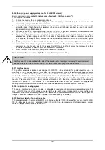
Page 26: ...ing Figure 6 Power supply 115 230 VAC b 24 VAC DC version Before commencing work note the instructions in Section 2 3 Before opening Then continue as follows 1 Remove the cover of the electronics comp...

Page 27: ...of T1 25A in accordance with IEC 127 3 5 Reassemble in reverse order points 3 through 1 Note the instructions of section 2 3 After opening during reassembling Figure 7 GFC 700 electronics unit with 2...

Page 28: ...g reassembling IMPORTANT Carefully keep the coaxial cables to the side of the housing while inserting or removing the electronics unit into respectively from the converter housing This is to prevent d...

Page 29: ...Power supply cable Cable parameters must be in accordance with the regulations in the EN 60079 14 Electrical installations in hazardous locations or an equivalent national standard e g DIN VDE 0165 R...

Page 30: ...8 5 CONNECTION DIAGRAM S1 gas sensor 1 S2 gas sensor 2 S3 gas sensor 3 S4 gas sensor 4 Gas sensors have type of protection flameproof enclosure EEx d EEx e junction box incl terminals EEx d cable gla...

Page 31: ...31 9 ATEX approvals 9 1 GFC 700 F EEx Signal converter...

Page 32: ...32...

Page 33: ...33...

Page 34: ...34 9 2 GFS 700 F EEx Primary head flowmeter...

Page 35: ...35...

Page 36: ...36...

Reviews: