background image

6

 OPERATION 

46 

H250

www.krohne.com

04/2009 - 4000269302   MA H250-R02

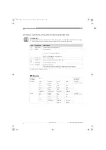
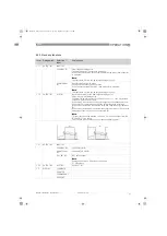
6.3  Overview of the most important functions and indicators

M10 flow units

M10 flow units

M10 flow units

M10 flow units

INFORMATION!

For a complete list of all functions and short descriptions  refer to Menu explanations on page 
51

. All default parameters and settings are adapted for the specific customer.

Level Designation

Explanation

1.4

TIME CONST.

Time constant, damping value [s]

1.5.2

ERROR

Error indicator

Yes: Error messages are deleted

No: Error messages are suppressed.

2.1

4-20mA OUT

Check current output

2.2 -

2.4

OUTPUT B

Check switching outputs and RESET input

3.1

LANGUAGE

Select the menu language

3.13.1

FLOW RATE

Maximum flow rate

The value set is represented by a 20 mA analogue current output.

If the current value exceeds the preset value, an alarm is indicated.

Table 6-4: The most important functions

Measured 
variables

Units

Measured 
products

Volume

m

3

/s

m

3

/min

m

3

/h

m

3

/d

Liquids, 
vapours, gases

L/s

L/min

L/h

-

ft

3

/s

ft

3

/min

ft

3

/h

ft

3

/d

gal/s

gal/min

gal/h

gal/d

bb/s

bb/min

bb/h

bb/d

ImpGal/s

ImpGal/min

ImpGal/h

ImpGal/d

Mass

g/s

g/min

g/h

-

Liquids, 
vapours, gases

kg/s

kg/min

kg/h

kg/d

-

t/min

t/h

t/d

lb/s

lb/min

lb/h

-

-

short t/min

short t/h

short t/d

-

-

long t/h

long t/d

MA_H250_R02_en_PRT.book  Page 46  Tuesday, September 22, 2009  12:26 PM

Summary of Contents for H250/C

Page 1: ...Variable area flowmeter H250 H250 H250 H250 Handbook Handbook Handbook Handbook KROHNE 04 2009 4000269302 MA H250 R02 MA_H250_R02_en_PRT book Page 1 Tuesday September 22 2009 12 26 PM...

Page 2: ...or written authorisation of KROHNE Messtechnik GmbH Co KG Subject to change without notice 2 H250 www krohne com 04 2009 4000269302 MA H250 R02 Copyright 2009 by KROHNE Messtechnik GmbH Co KG Ludwig K...

Page 3: ...stallation conditions 16 3 3 1 Tightening torques 17 3 3 2 Magnetic filters 18 3 3 3 Heat insulation 19 4 Electrical connections 20 4 1 Safety instructions 20 4 2 Electrical connection indicator M8 21...

Page 4: ...tructure 50 6 5 3 Menu explanations 51 7 Service 55 7 1 Maintenance 55 7 2 Replacement and retrofitting 55 7 2 1 Replacing floats 55 7 2 2 Retrofitting float damping 56 7 2 3 Retrofitting pointer damp...

Page 5: ...Directive 2004 108 EC Devices for use in hazardous areas ATEX Directive 94 9 EC as well as NAMUR recommendations NE 21 and NE 43 The manufacturer certifies successful testing of the product by applyin...

Page 6: ...e mail may involve gaps in security It is not possible to protect such data completely against access by third parties We hereby expressly prohibit the use of the contact data published as part of our...

Page 7: ...age to the device it is essential that you read the information in this document and observe applicable national standards safety requirements and accident prevention regulations If this document is n...

Page 8: ...partial disregard of this warning can lead to serious health problems and even death There is also the risk of seriously damaging the device or parts of the operator s plant WARNING Disregarding this...

Page 9: ...king list to check if you received completely all that you ordered INFORMATION Look at the device nameplate to ensure that the device is delivered according to your order Check for the correct supply...

Page 10: ...rinsically safe 2 H250 RR M10 Explosion proof enclosure 2 digital adjustable limit switches 2 wire open collector or type NAMUR 2 wire current output 4 20 mA HART communication Pulse output up to 10 H...

Page 11: ...lectronic bar graph indicator 2 wire current output 4 20 mA HART communication 2 H250 RR M8MG Local indication without auxiliary power supply 2 limit switches 2 wire type NAMUR or NAMUR safety oriente...

Page 12: ...m basically contains pointer damping An additional eddy current brake is advantageous for fluctuating or pulsing flows The eddy current brake magnets surround the pointer vane 1 without touching it da...

Page 13: ...ION Look at the device nameplate to ensure that the device is delivered according to your order Check for the correct supply voltage printed on the nameplate Figure 2 4 Nameplates on the indicator 1 D...

Page 14: ...standard indicator M9S Indicator with added impact and corrosion protection M9R Indicator in Stainless Steel housing M10 Indicator or signal converter M10 5 Design of indicator M8 MG Mechanical indic...

Page 15: ...ices is 40 80 C 40 176 F INFORMATION Inspect the cartons carefully for damage or signs of rough handling Report damage to the carrier and to the local office of the manufacturer INFORMATION Check the...

Page 16: ...ter of the flange deviates from the standard dimensions Flange seal standard DIN 2690 can be applied without any limitation Align the gaskets Tighten the nuts with the tightening torques of the approp...

Page 17: ...based on lateral installation of the display 3 3 1 Tightening torques For measuring devices with PTFE liner or ceramic liner and PTFE raised face tighten the flange threads with the following torques...

Page 18: ...in the flow direction upstream of the flowmeter Bar magnets are positioned helically in the filter to provide optimal efficiency at low pressure loss All of the magnets are coated individually with PT...

Page 19: ...lated The heat insulation 3 may only reach as far as the housing fastening 4 Figure 3 1 H250 heat insulation 1 Standard indicator M9 2 Indicator with HT extension CAUTION The heat insulation 1 may onl...

Page 20: ...ER For devices used in hazardous areas additional safety notes apply please refer to the Ex documentation WARNING Observe without fail the local occupational health and safety regulations Any work don...

Page 21: ...scale The pointers are set to the desired limit values using a slip coupling along the scale 4 2 2 Indicator M8E current output Figure 4 1 Limit switch settings M8MG 1 Maximum pointer switching point...

Page 22: ...tage can be calculated using the formula below Uext RL 22 mA 14 8 V where Uext the minimum supply voltage and RL the total measuring loop resistance is Figure 4 3 Electrical connection M8EG with elect...

Page 23: ...ns for AMS 6 x and PDM 5 2 as well as a DTM Device Type Manager are available for configuration They can be downloaded free of charge from our website The current flow rate can be transmitted using th...

Page 24: ...The switching points are set using the contact pointers The position of the contact pointer is indicated on the scale The connecting terminals have a pluggable design and can be removed in order to co...

Page 25: ...sired switching point After setting has been carried out Fix the contact pointers with the locking screw 3 Limit switch connection terminals 1 2 wire limit switch NAMUR 2 3 wire limit switch 3 Termina...

Page 26: ...e 3 wire limit switch does not have any wire break detection Current consumption in the position shown Switch contact definition 1 MIN contact 2 MAX contact 3 Pointer vane with switching vane Definiti...

Page 27: ...rcumstances internal connections in these devices e g GND with PE ground loops may lead to impermissible voltage potentials which can compromise the function of the device itself or a connected device...

Page 28: ...t impaired in any way Exception for multidrop mode In multidrop mode a maximum of 15 devices with HART function can be operated in parallel whereby their current outputs are switched inactive I approx...

Page 29: ...eliability When an error is detected a failure signal high is activated current 21 mA via the analogue output In addition more detailed information can be requested via HART CMD 48 The failure signal...

Page 30: ...ations see the chapter Technical data ESK3 PA In order to ensure optimum electromagnetic compatibility of systems it is important that the system components and in particular the bus cables are shield...

Page 31: ...jumper has to be connected to terminals S and S Pulse outputs P and P are electrically isolated A pulse is generated for each counter advance If the pulse output is not required its terminals can rema...

Page 32: ...moment of switch on Figure 4 7 Counter display modes 1 Flow rate as display 2 Flow totalizer display 3 Conversion factor display Figure 4 8 Settings of the counter at the moment of switch on RESET bu...

Page 33: ...nts lighting up Reset by pressing the RESET button Current input calibration Current input calibration Current input calibration Current input calibration During the switching on process keep the RESE...

Page 34: ...ing system 4 4 2 Power supply current output The electrical connection is reverse polarity protected Figure 4 11 Indicator M10 terminal connection 1 Power supply analog output 2 Switching output B1 3...

Page 35: ...can be calculated using the formula below Uext RL 22 mA 16 V where Uext the minimum supply voltage and RL the total measuring loop resistance is 1 Terminal connection 2 Converter supply isolator with...

Page 36: ...n DD Device Descriptions for AMS 6 x and PDM 5 2 as well as a DTM Device Type Manager are available for configuration They can be downloaded free of charge from our website The current flow rate can b...

Page 37: ...collector low resistance switching output with PNP technology Switching values CAUTION The switching outputs can only be operating if the power supply is applied to terminals I and I M10 switching out...

Page 38: ...d protective elements there is a voltage drop Uv for the load to be operated Switching capacity of B1 and B2 1 Max switching current I mA 2 Minimum load impedance RL Ohm 3 Power supply Uext Power loss...

Page 39: ...in the menu of the indicator INFORMATION When switching output B2 is used as a pulse output two separate signal circuits are required Each signal circuit requires its own power supply The total resis...

Page 40: ...ator M10 menu explanations If the input is set as ACTIVE LO an interruption causes the counter to be reset 4 5 Grounding connections Figure 4 14 Indicator M10 reset input 1 Function active HI 2 Functi...

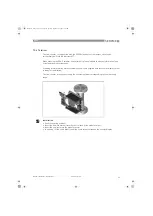
Page 41: ...e replaced The electrical cables used must be undamaged and must comply with regulations The cables must be laid with a loop 3 upstream of the measuring device to prevent water from getting into the h...

Page 42: ...the actual operating pressure and the product temperature of the system with the specifications on the nameplate PS and TS These specifications may not be exceeded Make sure materials are compatible S...

Page 43: ...the keys are represented as symbols to describe the operating functions CAUTION The switching point of the magnetic sensors is right at the level of the corresponding circle Only touch the circle ver...

Page 44: ...Open menu item and activate change mode In change mode In change mode In change mode In change mode Move the input cursor one position to the right after the last digit the input cursor jumps back to...

Page 45: ...sponses to keypad commands are faulty you have to do a hardware reset Switch the power supply OFF and ON again Save Yes Changes are accepted An update is carried out and the indicator jumps back to me...

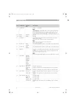
Page 46: ...Check current output 2 2 2 4 OUTPUT B Check switching outputs and RESET input 3 1 LANGUAGE Select the menu language 3 13 1 FLOW RATE Maximum flow rate The value set is represented by a 20 mA analogue...

Page 47: ...software are required or send the device back to the manufacturer for linearization FIRST NOT 0 The first flow value if the linearization table is not 0 LAST NOT 100 The last flow value if the linear...

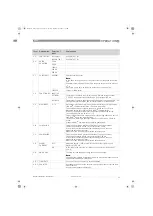
Page 48: ...polling address not equal to 0 using menu item 3 9 A polling address of 0 reactivates the current output CRYSTAL OSC FAULT Internal error in device Error The device must be sent back to the manufactur...

Page 49: ...t B1 NC contact 3 4 Function B2 INACTIVE 3 5 Contact B2 NC contact 3 6 Pulse duration 100ms 3 7 Pulse unit 001 liter 3 8 Function B3 INACTIVE 3 9 Multidrop polling address 0 3 12 Alarm current OFF 3 1...

Page 50: ...2 2 Output B1 2 3 Output B2 2 4 Input B3 2 5 Serial no 2 6 Software version 2 7 Tag no 3 3 3 3 Installation 3 1 Language 3 2 Function B1 3 3 Contact B1 3 4 Function B2 3 5 Contact B2 3 6 Pulse duratio...

Page 51: ...ching value of 200 is set under 1 1 1 then a hysteresis value of 0 200 can be set here If the value 0 is entered here then this output does not have hysteresis If the value 20 is entered here then the...

Page 52: ...sideration here CLOSED 2 4 INPUT B3 Here there is a visual depiction of whether or not input B3 has a voltage of 5 30 V If input B3 is set to ACTIVE HI in menu 3 8 then the display shows ON when the s...

Page 53: ...ling address is set to 0 then HART bus mode is switched off The device is working in analogue mode Current output 4 20 mA is active Standard HART communication remains guaranteed 3 10 4mA CALIBR This...

Page 54: ...low rate is 0 The current output is 4 00 mA 3 If the flow rate rises the current output remains at 4 00 mA 3 until the OFF value and is switched to the corresponding flow value if the flow value rises...

Page 55: ...upper snap ring out of the measuring unit Take the upper float stop and float out of the measuring unit Insert the new float into the centre hole of the lower float stop and push into the measuring u...

Page 56: ...he measuring unit Retrofit the supplied damping cylinder with the integrated float catcher 2 into the measuring unit Insert upper snap ring 1 7 2 3 Retrofitting pointer damping When retrofitting the p...

Page 57: ...e slightly in a clockwise direction 2 Check that the pointer vane can be moved between the magnets without touching them Screw in turnbuckle 2 7 2 4 Retrofitting limit switch Remove counter module if...

Page 58: ...ge product temperature product density viscosity or pressure is desired this can be done with the KroVaCal program or with a HARTTM modem However each measuring unit is subject to its own physical lim...

Page 59: ...oviding this information will ensure that the new scale supplied with the counter display cutout is ready for installation The flow counter is then preset using the conversion factor corresponding to...

Page 60: ...200 Set float stop gas damping PEEK X251050300 Damping bush 7x8 ZrO2 incl 2 span rings X251053100 Damping bush 7x8 PEEK incl 2 span rings X251053200 DN 25 DN 25 DN 25 DN 25 Float CIV 25 1 4404 X252041...

Page 61: ...span rings X254053200 Indicator M9 Indicator M9 Indicator M9 Indicator M9 Indicator housing complete no scale X251010000 Indicator complete stainless steel unpainted no scale X251011000 Cover M9 comp...

Page 62: ...on to the following points Due to statutory regulations on environmental protection and safeguarding the health and safety of our personnel manufacturer may only handle test and repair returned device...

Page 63: ...zardous toxic caustic flammable We checked that all cavities in the device are free from such substances We have flushed out and neutralized all cavities in the device We hereby confirm that there is...

Page 64: ...8EG 2 the flow dependent height of the float in the measuring unit is transmitted to the electronic display by magnetic field sensors S1 and S2 The flowmeters operate according to a modified float mea...

Page 65: ...uracy Directive VDI VDE 3513 sheet 2 qG 50 H250 RR HC F 1 6 H250 C Ceramic PTFE H250H H250U H250 100 1 2 5 Operating conditions Temperature Temperature Temperature Temperature Max operating temperatur...

Page 66: ...t Al2O3 and PTFE Al2O3 H250 F Food CrNi steel 1 4435 1 CrNi steel 1 4571 on request for clamp connection CrNi steel 1 4435 2 TFM PTFE liner electrically non conductive INFORMATION H250 C DN100 4 only...

Page 67: ...e limit switch 200 300 120 195 DN80 DN100 3 4 ESK2A ESK3 PA 200 300 150 250 ESK2A with counter 150 270 70 85 Limit switch NAMUR 200 300 200 300 3 wire limit switch 190 300 110 160 Maximum product temp...

Page 68: ...n product temperature Tm with limit switches 25 200 13 392 Ambient temperature Tamb 25 70 13 158 M8E Max product temperature Tm at Tamb 40 C 104 F 25 200 13 392 Max product temperature Tm at Tamb 50 C...

Page 69: ...n 4 mm2 Measuring signal 4 20 mA 0 100 flow value in 2 wire technology Power supply 14 8 30 VDC Min power supply for HART 20 5 VDC Power supply influence 0 1 Dependence on external resistance 0 1 Temp...

Page 70: ...C 8 VDC 8 VDC 10 30 VDC Pointer vane not detected 3 mA 3 mA 1 mA 0 3 VDC Pointer vane detected 1 mA 1 mA 3 mA UB 3 VDC Continuous current max 100 mA No load current I0 15 mA 1 safety oriented Terminal...

Page 71: ...l connection 2 5 mm2 Power supply 10 30 VDC Rext current loop 0 600 Ohm Power consumption max 2 5 Watt Indication error 1 in relation to the value displayed Max reset voltage 30 VDC Min reset pulse 30...

Page 72: ...ctronics 18 mA Accuracy acc to VDI VDE 3513 1 6 Measurement resolution 0 1 full scale value Temperature influence 0 05 K full scale value Software firmware version 1 01 000418 Ident No 3184980200 M9 E...

Page 73: ...0 1 Dependence on external resistance 0 1 Temperature influence 5 A K Max external resistance load 630 Ohm Min load for HART 250 Ohm Software firmware version 02 17 Ident No 3209470500 M10 HART Manufa...

Page 74: ...ses s NAMUR switch output Power supply 8 VDC Signal current 3 mA switching value not reached 1 mA switching value reached Switch output open collector Power supply 8 30 VDC Pmax 500 mW Imax 100 mA M10...

Page 75: ...2G Ex d IIC T6 T1 II3D Ex tD A22 IP66 T65 C FM M9 IS I 1 ABCD T6 NI I 2 ABCD T6 IS I II III 1 A G NI II 2 ABCD M10 XP I 1 ABCD T6 NI I 2 ABCD T6 XP I 1 IIC T6 NI I 2 IIC T6 DIP II III 1 EFG T6 S II II...

Page 76: ...DN15 110 5 4 35 107 4 22 20 0 79 100 3 94 187 7 37 DN25 1 110 5 4 35 119 4 69 32 1 26 106 4 18 199 7 84 DN50 2 123 5 5 22 132 5 20 65 2 56 120 4 73 212 8 35 DN80 3 123 5 5 22 148 5 83 89 3 51 145 5 7...

Page 77: ...143 5 63 132 5 20 55 2 17 DN80 3 147 5 79 83 3 27 160 6 30 132 5 20 55 2 17 DN100 4 147 5 79 83 3 27 169 6 66 132 5 20 55 2 17 Dimensions M8M Dimensions M8E f g h f g h EN ASME mm mm mm mm mm mm DN15...

Page 78: ...DN100 4 15 33 1 16 35 3 17 37 5 10 3 22 7 Standards Conn dim Pressure rating Flanges H250 RR HC C EN 1092 1 DN15 150 PN16 250 ASME B16 5 6 150 2500 lbs JIS B 2220 15 100 10 20K Clamp connections H250...

Page 79: ...12 21 15 DN50 PN40 2 4x M16 57 41 DN80 PN16 2 8x M16 47 34 DN100 PN16 2 8x M16 67 48 1 standard connections other connection on request 2 standard connections other connections on request Nominal size...

Page 80: ...5 3 55 63 1 1 5 12 21 26 K 15 4 80 100 1 7 2 2 12 21 26 K 15 5 120 160 2 5 3 6 12 21 26 K 15 6 200 250 4 2 5 5 12 21 26 K 15 7 350 400 700 6 7 10 18 1 12 21 28 38 K 15 8 500 630 1000 10 14 28 1 13 22...

Page 81: ...5 5 31 7 42 3 1 55 2 23 0 18 0 31 0 38 K 15 6 52 8 66 0 2 60 3 41 0 18 0 31 0 38 K 15 7 92 5 106 185 4 15 6 20 11 2 1 0 18 0 31 0 41 0 56 K 15 8 132 166 264 6 20 8 68 17 4 1 0 19 0 32 0 47 0 74 K 15 8...

Page 82: ...FE Ceramic Ceramic Nominal size Cone l h m3 h mbar DN15 E 17 2 25 30 65 62 62 E 17 3 40 50 1 8 66 64 64 E 17 4 63 70 2 4 66 66 66 E 17 5 100 130 4 68 68 68 E 17 6 160 200 6 5 72 70 70 E 17 7 250 250 9...

Page 83: ...7 2 6 60 7 93 0 96 0 91 0 91 E 17 3 10 6 13 2 1 12 0 97 0 94 0 94 E 17 4 16 6 18 5 1 49 0 97 0 97 0 97 E 17 5 26 4 34 3 2 48 1 00 1 00 1 00 E 17 6 42 3 52 8 4 03 1 06 1 03 1 03 E 17 7 66 0 66 0 5 58 1...

Page 84: ...ter l h Flow rate Air Nm3 h Pressure loss mbar DN15 K 15 1 70 1 8 195 K 15 2 120 3 204 K 15 3 180 4 5 195 K 15 4 280 7 5 225 K 15 5 450 12 250 K 15 6 700 18 325 K 15 7 1200 30 590 K 15 8 1600 40 950 K...

Page 85: ...scfm Pressure loss psig DN15 1 2 K 15 1 18 5 1 12 2 87 K 15 2 31 7 1 86 3 00 K 15 3 47 6 2 79 2 87 K 15 4 74 0 4 65 3 31 K 15 5 119 7 44 3 68 K 15 6 185 11 2 4 78 K 15 7 317 18 6 8 68 K 15 8 423 24 8...

Page 86: ...t Conversion to other media or operating data in accordance with VDE VDI Directive 3513 EN ASME Cone Flow rate Water l h Flow rate Air Nm3 h Pressure loss mbar DN15 K 15 1 65 1 6 175 K 15 2 110 2 5 17...

Page 87: ...media or operating data in accordance with VDE VDI Directive 3513 EN ASME Cone Flow rate Water gph Flow rate Air scfm Pressure loss psig DN15 K 15 1 17 2 0 99 2 57 K 15 2 29 1 1 55 2 62 K 15 3 44 9 2...

Page 88: ...or the oil and gas industry Measuring systems for sea going tankers Head Office KROHNE Messtechnik GmbH Co KG Ludwig Krohne Str 5 D 47058 Duisburg Germany Tel 49 0 203 301 0 Fax 49 0 203 301 10389 inf...

Reviews: