Installation and operating instructions
IFC 020
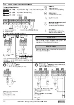
Field current line C (single shielding with IFC 020 F)
Line 2 x 0.75 mm
2
(18 AWG) Cu, 2 x 1.5 mm
2
(14 AWG) Cu or 2 x 2.5mm
2
(12 AWG) Cu
single shielding (Cu = copper cross section)
The cross section depends on the required cable length, see table in Section 1.3.4.
1/3
1.3 Electrical connection of separate primary heads (F- and E- versions)
1.3.1 General remarks on signal lines A and B and field current line C
Proper operation of the equipment is ensured when Krohne signal lines A and B are used with foil
screen and magnetic shield.
• Signal lines must be firmly installed.
• Shields are connected via stranded drain wires.
• Underwater or underground routing is possible.
• Insulating material flame-retardant to IEC 332.1 / VDE 0742.
• Low-halogen, unplasticized signal lines which remain flexible at low temperatures.
Signal line A
(type DS) with double shielding
1.3.2 Grounding of primary head
• All flowmeters must be properly grounded.
• The grounding conductor should not transmit any interference voltages.
• Do not ground any other electrical device together with this conductor.
• The primary head is connected to ground by means of an
FE functional ground conductor.
• Special information on grounding various primary heads is contained in the separate
installation instructions for primary heads.
• These instructions also contain detailed descriptions on how to use grounding rings and
how to install primary heads in metal or plastic pipes or internally coated pipelines.
1 Stranded drain wire, 1st shield, 1.5 mm
2
or AWG 14
2 Insulation
3 Stranded wire 0.5 mm
2
or AWG 20 (3.1 red/3.2 white)
4 Special foil, 1st shield
5 Insulation
6 Mu-metal foil, 2nd shield
7 Stranded drain wire, 2nd shield, 0.5 mm
2
or AWG 20
8 Outer sheath
Signal line B
(type BTS) with triple shielding (bootstrap line), for
IFC 020 E
only
1 Dummy glider wire
2 Insulation (2.1 red/2.2 white)
3 Special foil, 1st shield (3.1/3.2)
4 Insulation (4.1/4.2)
5 Stranded wire 0.5 mm
2
or AWG 20 (5.1 red/5.2 white)
6 Stranded drain wire, 1st shield, 0.5 mm
2
or AWG 20
(6.1/6.2)
7 Special foil, 2nd shield
8 Stranded drain wire, 2nd shield, 1.5 mm
2
or AWG 14
9 Insulation
10 Mu-metal foil, 3rd shield
11 Stranded drain wire, 3rd shield, 0.5 mm
2
or AWG 20
12 Outer sheath


