background image

2

 INSTALLATION 

OPTIFLUX 7300

www.krohne.com

10/2020 - 4008325701 - QS OPTIFLUX 7300 R03 en

2.7  General requirements

2.7.1  Vibrations

2.7.2  Magnetic field

INFORMATION!

The following precautions must be taken to ensure reliable installation.

Make sure that there is adequate space to the sides.

Protect the signal converter from direct sunlight and install a sun shade if necessary.

Signal converters installed in control cabinets require adequate cooling, e.g. by fan or heat 
exchanger.

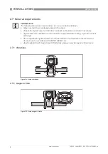
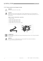
Do not expose the signal converter to intense vibration. The flowmeters are tested for a 
vibration level in accordance with EN/IEC 60068-2-64.

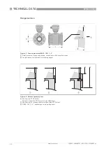
Avoid magnetic field! Keep at least 5 DN distance between electromagnetic flow sensor.

Figure 2-4: Avoid vibrations

Figure 2-5: Avoid magnetic fields

Summary of Contents for OPTIFLUX 7300

Page 1: ...tic flowmeter with non wetted electrodes and ceramic liner OPTIFLUX 7300 OPTIFLUX 7300 OPTIFLUX 7300 OPTIFLUX 7300 Quick Start Quick Start Quick Start Quick Start KROHNE 10 2020 4008325701 QS OPTIFLUX...

Page 2: ...lation conditions 9 2 8 1 Inlet and outlet 9 2 8 2 Bends in 2 or 3 dimensions 9 2 8 3 T section 10 2 8 4 Bends 10 2 8 5 Open discharge 11 2 8 6 Control valve 11 2 8 7 Pump 11 2 8 8 Air venting 12 2 8...

Page 3: ...e instructions can result in damage to the device or to parts of the operator s plant INFORMATION These instructions contain important information for the handling of the device CAUTION Installation a...

Page 4: ...ufacturer INFORMATION Do a check of the packing list to make sure that you have all the elements given in the order Figure 2 1 Scope of delivery 1 Ordered flowmeter sandwich or flanged version 2 Produ...

Page 5: ...ce with your order specifications The following version is available Compact version the signal converter is mounted directly on the measuring sensor INFORMATION Product specific information and exten...

Page 6: ...o ensure that the device is delivered according to your order Additional information e g correct supply voltage can be found in the documentation of the signal converter 1 Name and address of the manu...

Page 7: ...rature 50 70 C 58 158 F 2 5 Transport Compact version Do not lift the device by the signal converter housing Do not use lifting chains To transport the device use lifting straps 2 6 Pre installation r...

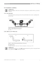
Page 8: ...sides Protect the signal converter from direct sunlight and install a sun shade if necessary Signal converters installed in control cabinets require adequate cooling e g by fan or heat exchanger Do no...

Page 9: ...owmeter Make sure the M12 connector is on the flow inlet side Figure 2 6 Recommended inlet and outlet sections 1 Refer to chapter Bends in 2 or 3 dimensions 2 t 2 DN Figure 2 7 2 and or 3 dimensional...

Page 10: ...08325701 QS OPTIFLUX 7300 R03 en 2 8 3 T section 2 8 4 Bends Figure 2 8 Distance after T sections 1 t 10 DN Figure 2 9 Installation in bending pipes 90 Figure 2 10 Installation in bending pipes 45 CAU...

Page 11: ...rohne com 10 2020 4008325701 QS OPTIFLUX 7300 R03 en 2 8 5 Open discharge 2 8 6 Control valve 2 8 7 Pump Figure 2 11 Installation before an open discharge Figure 2 12 Installation before control valve...

Page 12: ...4008325701 QS OPTIFLUX 7300 R03 en 2 8 8 Air venting 2 8 9 Temperatures Figure 2 14 Air venting 1 t 5 m 2 Air ventilation point Figure 2 15 Temperatures 1 Process temperature 2 Ambient temperature 3 S...

Page 13: ...m 10 2020 4008325701 QS OPTIFLUX 7300 R03 en 2 8 10 Flange deviation 2 8 11 Mounting position CAUTION Max permissible deviation of pipe flange faces Lmax Lmin d 0 5 mm 0 02 Figure 2 16 Flange deviatio...

Page 14: ...of max torque given in tables EN 1092 1 ASME B 16 5 WARNING Use stainless steel A2 6 9 class bolts Make sure the connecting flanges are of type raised face RF Figure 2 18 Tighten the bolts in fixed o...

Page 15: ...03 75 55 106 78 100 PN 25 M20 x 176 94 69 133 98 Nominal size DN inch Counter flanges bolts Max allowable torque Gasket Filled PTFE PTFE PF29 Gasket Graphite Rating Size Nm ftlb Nm ftlb 1 150 lb 1 2 U...

Page 16: ...in table WARNING Use stainless steel A2 6 9 class bolts CAUTION Please take care to use the proper gasket to prevent damaging the liner of the flowmeter In general the use of spiral wound gaskets is n...

Page 17: ...40 PN 40 4 x M 16 100 175 50 PN 40 4 x M 16 100 175 80 PN 40 8 x M 16 100 175 100 PN 16 8 x M 16 100 175 Nominal size DN inch Counter flanges Recommended torque ftlb Rating Bolts Min Max 1 150 4 x 40...

Page 18: ...rve without fail the local occupational health and safety regulations Any work done on the electrical components of the measuring device may only be carried out by properly trained specialists INFORMA...

Page 19: ...8325701 QS OPTIFLUX 7300 R03 en Grounding ring number 1 for type VN19 3 mm 0 12 thick tantalum 0 5 mm 0 02 3 3 Connection diagrams Figure 3 2 Grounding ring number 1 INFORMATION For the connection dia...

Page 20: ...d version a 155 mm 6 1 b 230 mm 9 1 1 c 260 mm 10 2 Total height H a 1 The value may vary depending on the used cable glands INFORMATION All data given in the following tables are based on standard ve...

Page 21: ...40 51 74 2 9 80 153 1 181 133 60 80 106 6 4 100 203 1 206 158 80 101 133 8 8 1 Total fitting length of flowmeter without rings dimension L only INFORMATION The table below is valid for 150 and 300 lb...

Page 22: ...4 1 Detail ceramics flange and gaskets see options in following illustration 2 Length tolerances see table on following pages Figure 4 3 Details of gasket options 1 Sealing ring PTFE white Optional c...

Page 23: ...0 184 165 40 51 9 80 200 217 200 60 80 15 100 250 242 220 80 101 21 Nominal size Dimensions inches Approx weight lb inch L H W D d1 1 5 91 5 47 4 25 0 79 1 02 8 8 1 5 91 6 18 5 00 1 18 1 54 13 2 2 7 8...

Page 24: ...g solutions Engineering commissioning calibration maintenance and training services Head Office KROHNE Messtechnik GmbH Ludwig Krohne Str 5 47058 Duisburg Germany Tel 49 203 301 0 Fax 49 203 301 10389...

Reviews: