2
INSTALLATION
24
OPTISONIC 1400
www.krohne.com
10/2016 - 4005626301 - QS OPTISONIC 1400 R01 en
•
3
Mount the drill to the flange of the valve
•
4
Carefully drill a hole in the pipe wall (Ø 45 mm). Make sure you use a fine notched Bi-Metal
or Tungsten Carbide hole saw, which leaves lesser burrs. Retract the drill including the cut
out piece of the pipe wall
•
Remove any remaining burrs from the in- and outside of the hole drilled.
•
5
Measure the distance y between the nozzle of the flange and the pipe inside. The distance y
depends on the welding process and includes the wall thickness of the pipe.
•
Adjust the distance between transducer end and the fitting of the flange to y, so after finishing
installation the transducer will be flush with the inner pipe wall.
•
Mark the position Z on the stem so the position of the transducer can always be checked after
fitting it on the pipe.
•
6
Mount the unit back onto the support flange. Tighten the bolts uniformly and in diagonally
opposite sequence. (do not exceed the maximum torque value of 14 Nm).
i
The marking Z is visible on the stem
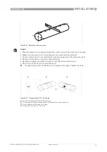
Figure 2-28: Installing the device; step 3 and 4
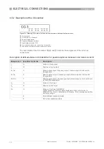
Figure 2-29: Installing the device; step 5 and 6


