120 °
1
2
3
1
-
2
3
-
4
5
4
12/2020 - 4008317001 - OPTISONIC 6300 F/…Ex R01 en
3
4
Go through menu X1...X5
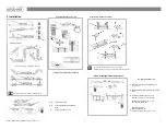
Greasing the transducer surfaces
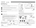
≥ 5 × ∅
Choose the applicable measuring
mode
Go through menu X1...X5
General installation of the rails
2 Installation
≥ 10 × ∅
Follow up with menu X7.2.4…X7.2.8
Run the optimization loop
The advised distance (menu X7.2.3)
must be > 246 mm / 9.7" for V-mode
Check the manual for more details on installation options
Check the OPTISONIC 6300 manual for more details on
installation options (e.g. Large version installation or applying solid pads)
Change the position of the transducer
Pump, control valve - open feed / discharge
Choose sensor size
Repeat if necessary.
Adjust settings in menu
X5 / X7 and finish with X7.2.9…7.2.11
Read the advised mounting distance in menu
X7.2.3
≥ 20 × ∅
Installation position
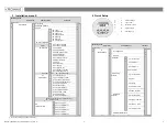
General configuration instructions
Enter the values for the installation menu,
X1...X7.2.8


