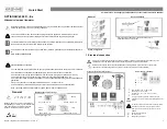
Measuring mode
1
Press > 2.5 s
↑ ↓
↑ ↓
↑ ↓ >
2
4
Signal strength
5
Operating keys
Measuring mode
Press > 2.5 s
↑ ↓
↑ ↓
1
↑ ↓
↑ ↓
↑ ↓
↑ ↓
↑ ↓
↑ ↓
↑ ↓
1
shows when configuring a 2 pipe installation
12/2020 - 4008317001 - OPTISONIC 6300 F/…Ex R01 en
5
6
X6 if pipe=2 at X4.1
X7.2.11 end installation
X7.2.9 path ready?
X7.2.2 number of traverses
` X7.2.3 mount transducers at
X7.2.4 act. flow, prelim.
X7.2.5 check signal
X7.2.6 actual distance
X7.2.7 optimize distance
X7.2.8 act.flow, prelim.
X Installation
X5 pipe data
Select menu
Select Submenu
↑ ↓ >
X3.6 density
X3.7 temperature
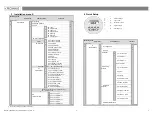
3 Installation menu X
Functions
X5.13 dynamic viscosity
X5.4 VoS pipe material
X5.5 wall thickness
X5.6 liner material
X5.7 velocity of sound
X3.4 [m3/s]*factor
X9.6 Tc calibration no.
X9.3 Tb serial no.
X9.4 Tb calibration no.
Ready? or next transducer? / install transd. 2 /
X8._ is identical to X7._
A5.1 measurement
X7.2.1 calibration number
X5.2 diameter
X4 pipe configuration
X5.3 pipe material
select
X4.1 number of pipes
X5.9 fluid
X5.10 VoS fluid
X5.11 density
X5.12 glycol % vol.
A5 Digital
Outputs
A6GDC IR interface
A3.1 reset errors
A3.2 totalizer 1
A3.3 totalizer 2
A3.4 totalizer 3
A4.1 measurement
A5.1 low fow cutoff
A4.5 time constant
A5.1 value p. pulse
A5.2 pulse value unit
X9.1 Ta serial no.
X9.2 Ta calibration no.
Functions
↑ ↓
Select menu
Select Submenu
X3.3 free unit
X3 units
Tag number
Status message
X9
transducer sets
4 Quick Setup
A4.2 unit
X4.2 number of paths
X9.5 Tc serial no.
A4.3 range
A4.4 low fow cutoff
A1 Language
3
Measured variable
X7.1 transducer set
X3.2 volume flow
X5.14 pipe temperature
X7
install transd. 1
X5.8 liner thickness
X6._: identical to X5._
X3.5 velocity
X1 language
X2 GDC IR interface
X3.1 size
A
Quick Setup
A2 Tag
A3 Reset
A4 Analog
Outputs
↵
>
↵
>
↵
↵
>
↵
>
↵
>
↵
>
↵
>
↵
>
↵
>
↵


