background image

Ultrasonic process gas flowmeter

ER 1.1.7_

OPTISONIC 7300

OPTISONIC 7300

OPTISONIC 7300

OPTISONIC 7300

Quick Start

Quick Start

Quick Start

Quick Start

© KROHNE 09/2018 - 4002312802 - QS OPTISONIC 7300 R04 en

Summary of Contents for OPTISONIC 7300

Page 1: ...ltrasonic process gas flowmeter ER 1 1 7_ OPTISONIC 7300 OPTISONIC 7300 OPTISONIC 7300 OPTISONIC 7300 Quick Start Quick Start Quick Start Quick Start KROHNE 09 2018 4002312802 QS OPTISONIC 7300 R04 en...

Page 2: ...2 9 3 Control valve 12 2 9 4 Flange deviation 12 2 9 5 Installation position 13 2 9 6 Thermal insulation 14 2 10 Mounting the field housing remote version 15 2 10 1 Pipe mounting 15 2 10 2 Turning th...

Page 3: ...ions can result in damage to the device or to parts of the operator s plant INFORMATION These instructions contain important information for the handling of the device CAUTION Installation assembly st...

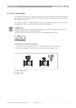
Page 4: ...ION The field device will arrive in two cartons One carton contains the converter and one carton contains the sensor Make sure to combine the correct devices together by comparing the serial numbers F...

Page 5: ...The factory settings for the operating data have been made in accordance with your order specifications The following versions are available Compact version the signal converter is mounted directly o...

Page 6: ...emperature 2 Space for additional information 3 Protection class and Tag number 4 Main supply and PED data 5 Calibration data and electronics revision number ER 6 Info web address and Rohs logo 7 Type...

Page 7: ...ient temperature 2 Space for additional information 3 Protection class and Tag number 4 Main supply and PED data 5 Calibration data and electronics revision number ER 6 Info web address and Rohs logo...

Page 8: ...nt devices P passive mode external power supply required for operation of the subsequent devices N C connection terminals not connected Figure 2 5 Example of a nameplate for electrical connection data...

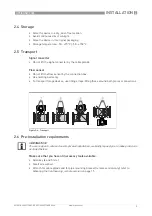
Page 9: ...lift the flow sensor by the connection box Use hoisting belts only To transport flange devices use lifting straps Wrap these around both process connections 2 6 Pre installation requirements Make sure...

Page 10: ...flow sensor in a horizontal position in a slightly descending line Orientate the flow sensor such that the path of the acoustic signal is in the horizontal plane For exchanging the transducers please...

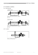
Page 11: ...tion conditions 2 9 1 Inlet and outlet 2 9 2 T section 1 path flowmeter Figure 2 8 Recommended inlet and oulet for d DN80 3 1 t 20 DN 2 t 3 DN 2 path flowmeter Figure 2 9 Recommended inlet and oulet f...

Page 12: ...iation CAUTION In case valve noise is expected large pressure drop over valve or pressure reducer in the same pipeline as the flowmeter please contact the manufacturer Figure 2 11 Not recommended inst...

Page 13: ...llation position Horizontal install the flow sensor in a horizontal position in case of the presence of liquids Vertically 15 15 15 15 D 15 15 15 15 Horizontal or vertical allowed installation positio...

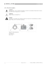
Page 14: ...ompletely except for the transducers 1 and the connection box 2 to allow cooling by free air convection WARNING Always leave vent holes 3 free DANGER For devices in hazardous area additional maximum t...

Page 15: ...ing 1 Fix the signal converter to the pipe 2 Fasten the signal converter using standard U bolts and washers 3 Tighten the nuts INFORMATION Assembly materials and tools are not part of the delivery Use...

Page 16: ...Pull out the display and rotate it to the required position 3 Slide the display back into the housing 4 Re fit the cover and tighten it by hand Figure 2 17 Turning the display of the field housing ver...

Page 17: ...e nameplate DANGER Observe the national regulations for electrical installations DANGER For devices used in hazardous areas additional safety notes apply please refer to the Ex documentation WARNING O...

Page 18: ...oth functioning always use the signal cable s included in the delivery Figure 3 2 Clamp the cables on the shielding bush 1 Cables 2 Cable glands 3 Grounding clamps 4 Cable with metal shielding bush Fi...

Page 19: ...cuit breaker and wiring has to be suitable for the application and shall also be in accordance with the local safety requirements of the building installation e g IEC 60947 1 3 DANGER For devices used...

Page 20: ...VAC DC tolerance range AC 15 10 DC 25 30 24 VAC DC tolerance range AC 15 10 DC 25 30 24 VAC DC tolerance range AC 15 10 DC 25 30 Note the data on the nameplate For measurement process reasons a functi...

Page 21: ...ith various output modules Current outputs can be active or passive Optionally available also with Foundation Fieldbus Modular version Depending on the task the device can be configured with various o...

Page 22: ...ay modular I O Ia Pa Sa and optional module Pp Sp Ip Abbreviation Identifier for CG no Description Ia A Active current output Ip B Passive current output Pa Sa C Active pulse output frequency output s...

Page 23: ...ve 2 Ia HART active 1 Ex i I Os option 2 0 0 Ia HART active PN SN NAMUR 2 3 0 0 Ip HART passive PN SN NAMUR 2 2 1 0 Ia active PN SN NAMUR Cp passive 2 Ia HART active PN SN NAMUR 2 3 1 0 Ia active PN S...

Page 24: ...ax 2 optional modules for term A B Ia HART active Pa Sa active 1 8 _ _ max 2 optional modules for term A B Ip HART passive Pa Sa active 1 6 _ _ max 2 optional modules for term A B Ia HART active Pp Sp...

Page 25: ...and weight Remote version Remote version Remote version Remote version a 88 mm 3 5 b 139 mm 5 5 1 c 106 mm 4 2 Total height H a Compact version Compact version Compact version Compact version a 155 m...

Page 26: ...350 PN 10 610 519 542 341 109 400 PN 10 640 575 583 392 141 450 PN 10 620 625 623 442 170 500 PN 10 670 678 670 493 202 600 PN 10 790 784 780 593 278 Table 4 1 Dimensions and weight in mm and kg 1 Di...

Page 27: ...2 15 0 380 8 3 210 12 2 310 2 5 63 33 15 3 20 5 520 8 9 226 12 8 324 3 1 78 44 20 4 21 7 550 10 1 258 13 3 337 4 0 102 64 29 5 23 2 590 11 2 285 14 1 364 5 1 128 84 38 6 24 4 620 12 2 312 15 2 387 6...

Page 28: ...5 851 36 0 914 22 6 575 1715 778 Table 4 5 Dimensions and weight in inch mm and lb kg 1 Di inner diameter at flange face Inner tube diameter may be smaller Nominal size Dimensions Approx weight L H W...

Page 29: ...6 600 9 9 251 12 5 324 2 6 67 119 54 4 26 8 640 11 4 290 13 0 337 3 4 87 157 71 5 26 8 680 12 6 333 13 7 359 4 6 116 240 109 6 28 7 730 14 3 363 15 0 381 5 5 140 335 152 8 26 8 680 17 0 433 18 5 470...

Page 30: ...F remote version Version Dimensions mm Weight kg a b c d e g h C 202 120 155 260 137 4 2 F 202 120 155 295 8 277 5 7 Table 4 8 Dimensions and weight in mm and kg Version Dimensions inch Weight lb a b...

Page 31: ...7300 www krohne com 09 2018 4002312802 QS OPTISONIC 7300 R04 en 4 1 3 Mounting plate of field housing Figure 4 3 Dimensions for mounting plate of field housing mm inch a 72 2 8 b 72 2 8 c 9 0 4 Table...

Page 32: ...rvices Head Office KROHNE Messtechnik GmbH Ludwig Krohne Str 5 47058 Duisburg Germany Tel 49 203 301 0 Fax 49 203 301 10389 info krohne com KROHNE 09 2018 4002312802 QS OPTISONIC 7300 R04 en Subject t...

Reviews: