background image

5

 OPERATION 

22 

OPTISYS CL 1100

www.krohne.com

03/2016 - 4002492302 - MA OPTISYS CL 1100 R03 en

C1.18.3

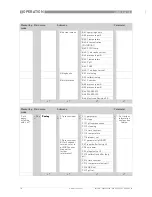
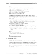
temp. coefficient

Temperature coefficient for manual temperature compensation during 

calibration.

C1.18.4

pH compensation

Options:

off: pH measurement is disabled

manual: pH value has to be entered manually

automatic: pH measurement is performed as configured

C1.18.5

man. pH compensation

If in menu C1.18.4 the pH compensation was set to manual, here the desired 

pH value is entered manually.

C1.18.6

start calibration

Start calibration procedure.

C1.18.7

stored value

View stored value of calibration.

C1.18.8

reference

Enter the reference value of the probe in mg/l.

CAUTION!

If you choose for measurement the temperature compensation "linear" than choose between 
"automatic" or "manual" for the temperature compensation during calibration. If you choose for 
measurement the temperature compensation "off" than choose also "off" for the temperature 
compensation during calibration.

Level

Designation / function

Settings / descriptions

Summary of Contents for OPTISYS CL 1100

Page 1: ...CL 1100 OPTISYS CL 1100 OPTISYS CL 1100 OPTISYS CL 1100 Handbook Handbook Handbook Handbook KROHNE 03 2016 4002492302 MA OPTISYS CL 1100 R03 en The documentation is only complete when used in combina...

Page 2: ...any part thereof without the prior written authorisation of KROHNE Messtechnik GmbH Subject to change without notice 2 www krohne com 03 2016 4002492302 MA OPTISYS CL 1100 R03 en Copyright 2016 by KRO...

Page 3: ...l notes on installation 12 3 2 Storage and transport 12 3 3 Pre installation requirements 12 3 4 Installing the system 13 3 4 1 Mounting of the OPTISYS CL 1100 measuring system 13 3 5 Examples of a ty...

Page 4: ...ing 36 6 1 3 Aging and re calibration 37 6 2 Spare parts availability 37 6 3 Availability of services 37 6 4 Returning the device to the manufacturer 38 6 4 1 General information 38 6 4 2 Form for cop...

Page 5: ...successful testing of the product by applying the CE marking CAUTION Responsibility for the use of the measuring devices with regard to suitability intended use and corrosion resistance of the used m...

Page 6: ...over the Internet e g when communicating by e mail may involve gaps in security It is not possible to protect such data completely against access by third parties We hereby expressly prohibit the use...

Page 7: ...on To prevent any injury to the user or damage to the device it is essential that you read the information in this document and observe applicable national standards safety requirements and accident p...

Page 8: ...warnings must be observed without fail Even partial disregard of this warning can lead to serious health problems and even death There is also the risk of seriously damaging the device or parts of the...

Page 9: ...N Inspect the packaging carefully for damages or signs of rough handling Report damage to the carrier and to the local office of the manufacturer INFORMATION Do a check of the packing list to make sur...

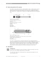
Page 10: ...temperature sensor for compensation As an option a pH measurement can be added in a third flow through cell The Automatic Sensor Cleaning ASR Patent Dr A Kuntze is part of the standard device All sens...

Page 11: ...ounds and hydrogen reduces rust and manganese oxide and likewise destroys organic coatings The ASR considerably increases the life span of the sensors achieving high measuring stability with extremely...

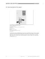
Page 12: ...chlorine system Ensure for the measuring point that the process or the by pass is switched off there is sufficient working space available for operation of the system the process connection hose and...

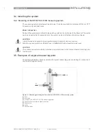
Page 13: ...or basin 3 5 Examples of a typical measuring point The following drawing show an example of a typical measuring point consisting of a sensor and the flow through assembly CAUTION Install the device a...

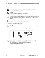
Page 14: ...the power disconnected Take note of the voltage data on the nameplate DANGER Observe the national regulations for electrical installations WARNING Observe without fail the local occupational health a...

Page 15: ...signal converter by the manufacturer INFORMATION Look at the device nameplate to ensure that the device is delivered according to your order Check for the correct supply voltage printed on the namepla...

Page 16: ...erminals of terminal block Pos A as described in the previous drawing table To remove a cable press down the white clip 7 on the corresponding terminal and pull the cable out 4 4 Connecting the extern...

Page 17: ...ference A12 ORP calibration B Only if switched Only if switched Only if switched Only if switched to ORP to ORP to ORP to ORP process input B ORP calibration for 2 channel version refer to pH ORP sens...

Page 18: ...B6 5 SW REV UIS B6 6 Electronic Revision ER Measuring mode Main menu Submenu Parameter 3 or 4 pages scrolling with or 2 5 s C setup C setup C setup C setup C1 process input A C1 1 parameter For furthe...

Page 19: ...im process inp B INFORMATION Note that the appearance of some sub menus depends on the hardware setting and the used sensor s Also only the sensor relevant menus and submenus are shown here in detail...

Page 20: ...onverter has two process inputs A and B Each process input has an own submenu in this main menu Process input A is always present i e there is always a board in the interface Pos A in the connection a...

Page 21: ...of old value hold time is retriggered up to two times C1 13 4 clean Start cleaning procedure manually C1 15 C1 15 C1 15 C1 15 C2 15 C2 15 C2 15 C2 15 temperature Menu for temperature measurement Avail...

Page 22: ...pH compensation was set to manual here the desired pH value is entered manually C1 18 6 start calibration Start calibration procedure C1 18 7 stored value View stored value of calibration C1 18 8 refe...

Page 23: ...ion is disabled The menu for the type of linear temperature probes offer the following options Pt1000 Pt1000 Pt1000 Pt1000 choose this option if there is an external Pt1000 temperature sensor connecte...

Page 24: ...display setup and C1 appears beneath the submenu process input A process input A process input A process input A is highlighted Press to enter the chosen menu You are on the second submenu level In th...

Page 25: ...ds then release the button You are now on the main menu level Press or until the main menu setup setup setup setup is highlighted MAIN MENU A quick setup B test C setup C setup C setup C setup D servi...

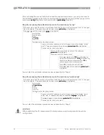
Page 26: ...around pH 7 If the pH compensation is disabled and you use a reference method like DPD which compensates the pH influence you calibrate this difference in Hence if the pH value now changes the calibra...

Page 27: ...tomatic and the manual function compensate the displayed value of the free chlorine concentration to 100 HClO at pH 6 0 Hence for a correct calibration the reference value should compensate the pH val...

Page 28: ...er has a hold function This function freezes all outputs i e the display and the current outputs on the last measured value After starting up the signal converter the measuring screen appears This is...

Page 29: ...sample vessel Press for more than 2 5 seconds then release the button You are on the main menu level In the upper line on the right side of the display A appears beneath the main menu quick setup qui...

Page 30: ...beneath the submenu process input A process input A process input A process input A is highlighted Press to enter the chosen menu You are on the second submenu level The submenu parameter parameter p...

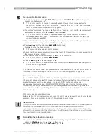
Page 31: ...asurement which takes 25 seconds Carry out the next action during this time To perform a successful calibration please consider the installation of the sensor for detailed information refer to Mountin...

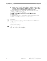
Page 32: ...l converter now asks store value store value store value store value Using or choose yes yes yes yes to store the calibration values or no no no no to discard them Press to confirm Press several times...

Page 33: ...appears beneath the main menu quick setup quick setup quick setup quick setup is highlighted Press or until the main menu test test test test is highlighted MAIN MENU A quick setup B test B test B tes...

Page 34: ...nsor with a soft cloth For further information refer to Automatic sensor cleaning on page 35 Flow velocity is not stable Regulate and stabilise the flow velocity The sensor slope appears to be too sma...

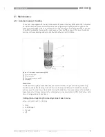
Page 35: ...the measuring medium until it reaches the end of its lifetime Hold time Due to the cleaning the polarisation layer becomes disturbed To prevent wrong measuring results caused by the cleaning the hold...

Page 36: ...terminal D configured as control input Setup I O hardware terminals D control input Afterwards the control input has to be selected as cleaning Setup I O terminals D mode control input The cleaning i...

Page 37: ...lope of the sensor and the sensor limits are displayed after each calibration procedure 6 2 Spare parts availability The manufacturer adheres to the basic principle that functionally adequate spare pa...

Page 38: ...safeguarding the health and safety of the personnel the manufacturer may only handle test and repair returned devices that have been in contact with products without risk to personnel and environment...

Page 39: ...ice when it is returned Date Signature Stamp CAUTION Disposal must be carried out in accordance with legislation applicable in your country Separate collection of WEEE Waste Electrical and Electronic...

Page 40: ...the polarising layer is not changed Free chlorine molecules that hit the surface of the measuring electrode take a defined portion of the charge with them changing the measuring potential The signal...

Page 41: ...ne gas Cl2 between pH3 and pH8 Hypochlorous acid HClO above pH8 Hypochlorite ClO In order to obtain a reliable free chlorine measurement you should either control or compensate the pH value of the mea...

Page 42: ...molecule s unpaired electron is transferred to the DNA of the microorganism which cracks and causes cell necrosis ClO2 has a long term effect of several days In contrast to chlorine the disinfection...

Page 43: ...lectivity towards ozone A precise potential is built up between the measuring and the reference electrode The measuring electrode starts polarising i e ions collect close to the electrode to neutraliz...

Page 44: ...allation with sample feed Ingress protection for housing IP66 67 acc to NEMA 4 4X Sample flow connections Tube connection DN6 8 Drill hole 10 mm 0 39 Measuring accuracy Reference conditions Medium wat...

Page 45: ...can be adjusted Current output Three isolated outputs 4 20 mA all galvanic isolated errors signals 3 25 mA and 22 mA active mode Output data depending on sensor Operating data Uint nom 15 VDC I 0 4 2...

Page 46: ...AL DATA 46 OPTISYS CL 1100 www krohne com 03 2016 4002492302 MA OPTISYS CL 1100 R03 en 7 3 Dimensions and weights for the system Weight 5 15 kg 11 35 lb Dimensions mm inch a 700 27 56 b 400 15 75 c 10...

Page 47: ...NOTES 8 47 OPTISYS CL 1100 www krohne com 03 2016 4002492302 MA OPTISYS CL 1100 R03 en...

Page 48: ...vices Head Office KROHNE Messtechnik GmbH Ludwig Krohne Str 5 47058 Duisburg Germany Tel 49 203 301 0 Fax 49 203 301 10389 info krohne com KROHNE 03 2016 4002492302 MA OPTISYS CL 1100 R03 en Subject t...

Reviews: