background image

5

 OPERATION 

34 

OPTISYS TUR 1050

www.krohne.com

02/2017 - 4002444302 - MA OPTISYS TUR 1050 R03 en

•  

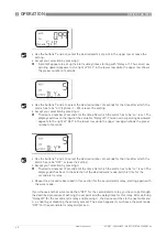
Press

^

 to accept the new operational status.

i

The display now shows the set offset value (default setting is 0.00).

•  

Select the desired offset value by pressing

 or

 (regard the example below).

•  

Press

^

 to accept the chosen offset value.

i

The offset calibration is complete and the device goes to the next submenu in the 
configuration main menu.

•  

If you want to return to the normal measuring mode, press MODE/EXIT.

Example of finding out the offset value

The correct offset value is the difference between the value measured with the turbidity meter 
for laboratory use and the value measured with the actual meter. After you have entered an 
offset value, the meter adds or subtracts this value from its own measured value (depending on 
the algebraic sign of the difference).

If the actual meter measures 0.28 NTU/FNU in the grab sample and the meter for laboratory use 
measures 0.04 NTU in the same sample, than the correct offset value is -0.24. After entering the 
offset value the device subtracts 0.24 from its own measured value of 0.28 NTU/FNU and 
displays a measuring result of 0.04 NTU/FNU.

INFORMATION!

Whenever the measurement rests upon an offset value, the information "OFFSET" appears in the 
lower right corner of the display (even in the normal operation mode).

Summary of Contents for OPTISYS TUR 1050

Page 1: ...Compact measuring system for turbidity OPTISYS TUR 1050 OPTISYS TUR 1050 OPTISYS TUR 1050 OPTISYS TUR 1050 Handbook Handbook Handbook Handbook KROHNE 02 2017 4002444302 MA OPTISYS TUR 1050 R03 en...

Page 2: ...any part thereof without the prior written authorisation of KROHNE Messtechnik GmbH Subject to change without notice 2 www krohne com 02 2017 4002444302 MA OPTISYS TUR 1050 R03 en Copyright 2017 by KR...

Page 3: ...1 General notes on installation 14 3 2 Storage and transport 14 3 3 Requirements of the device 14 3 4 Installation order 15 3 4 1 Placing the desiccant pouch and the humidity indicator 15 3 4 2 Selec...

Page 4: ...guring the RS 485 port 38 5 7 4 Configuring the alarm relays 39 5 7 5 Offset calibration 41 5 7 6 Enabling or disabling the security access 41 5 7 7 Extended settings 41 5 8 Restoring the factory sett...

Page 5: ...tandard and immunity for industrial environments Low Voltage Directive Safety requirements for electrical equipment for measurement control and laboratory use in accordance with EN 61010 1 2001 Editio...

Page 6: ...n over the Internet e g when communicating by e mail may involve gaps in security It is not possible to protect such data completely against access by third parties We hereby expressly prohibit the us...

Page 7: ...ion To prevent any injury to the user or damage to the device it is essential that you read the information in this document and observe applicable national standards safety requirements and accident...

Page 8: ...warnings must be observed without fail Even partial disregard of this warning can lead to serious health problems and even death There is also the risk of seriously damaging the device or parts of th...

Page 9: ...e that the device is delivered according to your order Check for the correct supply voltage printed on the nameplate INFORMATION Assembly materials and tools are not part of the delivery Use the assem...

Page 10: ...tubing 4 Backpressure valve allows adjustment of the amount of back pressure which helps to control the flow rate and elim inate small bubbles 5 Display LCD 6 Operation keys 7 Drain hose connection i...

Page 11: ...air a fan inside the device continuously circulates this heated and by the desiccant pouch dehumidified air around the optical well and the electronic device This features eliminates the need for a dr...

Page 12: ...rams are Hilgraeve hyperterminal included in most Microsoft Windows packages or Visual Basic Ultrasonic cleaning This feature helps to clean the ultrasonic cuvette continuously The system works by sen...

Page 13: ...02 MA OPTISYS TUR 1050 R03 en White light version Figure 2 5 Example for nameplate for white light version 1 Manufacturer and address 2 WEEE waste bin symbol 3 ETL symbol 4 CE symbol 5 Logistics numbe...

Page 14: ...psi built in regulator set at 1 bar 15 psi Maximum allowable flow rate of the cuvette 0 1 1 l min 0 026 0 26 gal min Maximum fluid temperature 50 C 122 F INFORMATION Inspect the packaging carefully fo...

Page 15: ...thin the upper part of the device after removing you can discard the tube CAUTION Installation assembly start up and maintenance may only be performed by appropriately trained personnel The regional o...

Page 16: ...nds and reconnecting it 3 4 2 Selecting site and mounting The preferred way of mounting of the device is wall mounting If this is not possible you can mount the device on any suitable level surface Ir...

Page 17: ...sions there differ from reality Drill six holes into the mounting surface and insert six screw anchors into them Use screws M4 3 16 to fix the junction box power assembly at first Put the electronic d...

Page 18: ...0 www krohne com 02 2017 4002444302 MA OPTISYS TUR 1050 R03 en 3 4 3 Mounting mm a 51 2 0 b 147 5 79 c 90 3 54 d 87 3 43 CAUTION Please do not use this directly as mounting template as the printed dim...

Page 19: ...flow drain do not belong to the scope of delivery For this purpose use hoses with the following specifications Inner diameter 4 75 mm 3 16 Outer diameter 8 mm 5 16 Flexible and opaque hose material to...

Page 20: ...kage at the drain vent hole Therefore the scope of delivery contains a seal screw that you can insert into the vent hole and tighten Figure 3 4 Procedure to assemble the plumbing and connect the hoses...

Page 21: ...the cuvette with a soft cloth just before inserting it The dehumidification system cannot remove large droplets of water only residual moisture Figure 3 5 Procedure for inserting and fixing the ultra...

Page 22: ...NGER Observe the national regulations for electrical installations WARNING Observe without fail the local occupational health and safety regulations Any work done on the electrical components of the m...

Page 23: ...rgise all cables before starting any installation or service work otherwise a perilous electric shock can happen CAUTION The device has a switching power supply which demands 100 240 VAC and 47 63 Hz...

Page 24: ...properly sealed DANGER The device involves a line voltage that could endanger life Only qualified electricians are allowed to perform the electrical installation of the device Always note all local an...

Page 25: ...lex digital interface 2 wire operates with differential levels that are unsusceptible to electrical interferences This is why the usage of cable lengths up to 900 m 2950 ft is possible Independent of...

Page 26: ...e following figure 4 5 4 Connecting the sensor interconnect cable Figure 4 3 Signal output connection RS485 4 20 mA CAUTION Always connect the sensor interconnect cable with the upper part of the devi...

Page 27: ...ice Switch on the power supply Wait until the device has completed its warm up 1 hour during the initial start up and typically 45 minutes during all following start ups at the same time the fully aut...

Page 28: ...lower row displays the current scale and the upper row the measured reading The following drawing is an example for a display during normal operation Figure 5 1 Description of the display and operatin...

Page 29: ...eady pressed the button MODE EXIT press it now in the normal measuring mode 1 x CAL 2 x CONFIG i You see the display like in the drawing above with the first number of the access code in the upper row...

Page 30: ...urer calibrates and tests every device before it leaves the factory Therefore you can use the device directly out of the box Under normal conditions the manufacturer recommends a recalibration every t...

Page 31: ...uvette accounts for normal scratches and aberrations in the cuvette glass when performing a calibration The manufacturer supplies all his optionally available calibration cuvettes with indexing rings...

Page 32: ...justment slowly rotate the calibration cuvette about 5 clockwise and counterclockwise to find the lowest measured turbidity After finding out the lowest measured value of the 100 NTU FNU or 1000 NTU F...

Page 33: ...Compare the turbidity values of both samples If they are very close then an offset calibration is not required and you can stop the procedure at this step If both samples differ substantially but les...

Page 34: ...erence between the value measured with the turbidity meter for laboratory use and the value measured with the actual meter After you have entered an offset value the meter adds or subtracts this value...

Page 35: ...fic needs any time during normal operation with the help of the configuration mode Be aware of the following device properties As described in the section Menu topology you have to press the button MO...

Page 36: ...or options 4 20 for the 4 20 mA output 485 for the RS 485 output OFF if you do not need outputs or leave the setting The displays for the two possible outputs look like the following drawings Accept...

Page 37: ...ce switches to the next menu item i e the setting of the upper limit Use the buttons and to define the upper turbidity limit which is assigned to the 20 mA output level or leave the setting Accept you...

Page 38: ...lection by pressing i The device switches to the next menu item i e the setting of the device address Use the buttons and to select the desired device address or leave the setting options 1 255 Accept...

Page 39: ...point just for a short time There are two options Delay on Delay on Delay on Delay on with this option you can define a time period the turbidity level must exceed the alarm set point for this time p...

Page 40: ...the right of DLY in the lower row while the upper row again shows the preset number of seconds Use the buttons and to select the desired number of seconds for the time after which the alarm has to be...

Page 41: ...he buttons or to enable upper row ON or disable upper row OFF the security access or leave the setting i If you enabled the security access the security key icon will be visible and flashing on the di...

Page 42: ...e 20 mA adjustment will switch the device back to the normal measuring mode AUTO all settings are saved Speed of response With the help of this function you can adjust the speed of response for both t...

Page 43: ...t of the decimal place are not stable you can reduce the resolution i e the amount of digits right to the decimal place to hide these digits and get a stable reading Display backlight brightness The d...

Page 44: ...page 36 In this case you can change the parameters BITS PRTY parity and STOP stop bit After choosing a setting for the ultrasonic cleaning in the previous step you see the following display at first U...

Page 45: ...tes the alarms and sets the 4 20 mA output to the selected error level In the normal measuring mode you see the measured value in the upper row and DESC in the lower row Enquiries of master computer A...

Page 46: ...xactly 4 mA or 20 mA at your multimeter or control system This settings will be slightly different on each device as the manufacturer sets them to 4 00 mA and 20 mA before shipping The limits are 4 mA...

Page 47: ...e any alarms If for example the desiccant becomes saturated and the desiccant alarm is disabled the warning DESC appears on the display Errors The cause of an error message can usually be corrected by...

Page 48: ...is a complete malfunction i e the device does not function properly Failures cannot be corrected by the operator but the device has to be returned to the manufacturer They concern internal systems su...

Page 49: ...AIL FAIL FAIL FAIL bottom row of display Failure Complete malfunction of an internal system Return the device to the manufacturer FLOW FLOW FLOW FLOW bottom row of display only if flow switch is insta...

Page 50: ...nly be performed by appropriately trained personnel The regional occupational health and safety directives must always be observed INFORMATION Each time a housing cover is opened the thread should be...

Page 51: ...because of to much moisture or water on the cuvette the message DESC appears on the display 6 2 2 Replacing desiccant pouch and humidity indicator The device monitors the replaceable desiccant pouch c...

Page 52: ...sembly XGA M 010015 Pressure regulator XGA M 010020 Junction box power assembly XGA M 010025 Ultrasonic cuvette XGA M 010030 Lamp assembly WL XGA M 010040 Lamp assembly IR XGA M 010050 Tubing kit 1 dr...

Page 53: ...uarding the health and safety of the personnel the manufacturer may only handle test and repair returned devices that have been in contact with products without risk to personnel and environment This...

Page 54: ...vice when it is returned Date Signature Stamp CAUTION Disposal must be carried out in accordance with legislation applicable in your country Separate collection of WEEE Waste Electrical and Electronic...

Page 55: ...asured with the 90 scattered light method Light source and receiver are positioned in a 90 angle to each other The light transmitted from the source is directed in equal strength to the reference rece...

Page 56: ...and US EPA 180 1 Measuring range 0 02 100 NTU FNU or 0 02 1000 NTU FNU Design The measurement system consists of a sensor and a signal converter and is only available as compact version Display and u...

Page 57: ...on category Enclosure is designed to meet IP 66 NEMA 4X Installation conditions Dimensions For detailed information refer to Dimensions and weight on page 58 Weights Shipping weight 2 5 kg 5 5 lbs Mat...

Page 58: ...www krohne com 02 2017 4002444302 MA OPTISYS TUR 1050 R03 en 7 3 Dimensions and weight Shipping weight 2 5 kg 5 5lbs Dimensions mm a 208 8 19 b 51 2 0 c 90 3 54 d 30 1 18 e 87 3 43 f 148 5 83 g 131 5...

Page 59: ...NOTES 8 59 OPTISYS TUR 1050 www krohne com 02 2017 4002444302 MA OPTISYS TUR 1050 R03 en...

Page 60: ...vices Head Office KROHNE Messtechnik GmbH Ludwig Krohne Str 5 47058 Duisburg Germany Tel 49 203 301 0 Fax 49 203 301 10389 info krohne com KROHNE 02 2017 4002444302 MA OPTISYS TUR 1050 R03 en Subject...

Reviews: