background image

03/2012 - 4001904901 - HB OPTIWAVE 5200 R01 en 

www.krohne.com 

13 

  OPTIWAVE 5200 C/F  

INSTALLATION 

3


3.5  Installation 


3.5.1  Pressure and temperature ranges 


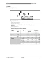
Figure 3-2: Pressure and temperature ranges 

Flange temperature 

Non-Ex devices: Depends on the type of antenna, process connection and the seal material. Refer to the table that fol- lows. 
Ex devices: see supplementary operating instructions 

Ambient temperature for operation of the display 

-20...+60

°

C / -4...+140

°

If the ambient temperature is not between these limits, the display screen switches off automatically. The device con- tinues to operate. 

Ambient temperature 

Non-Ex devices: -40...+80

°

C / -40...+176

°

Ex devices: see supplementary operating instructions 

Process pressure 

Depends on the type of antenna and process connection. Refer to the table that follows. 


Antenna type


Process 

connection


Seal


Process connection 

temperature


Process pressure


[

°

C]


[

°

F]


[barg]


[psig]


PP Wave Horn


G 1

½

1

½ 

NPT


-


-20...+100


-4...+212


-1...16 

1


-14.5...232 

1


PTFE Wave Horn


Flange with 

PTFE plate


-


-50...+150


-58...+302


-1...34 

1


-14.5...493 

1


Metallic Horn 

Wave Guide


Flange


Metaglas

® 

with 

FKM/FPM


-40...+200


-40...+392


-1...40 

1


-14.5...580 

1


Metaglas

® 

with 

Kalrez

® 

6375


-20...+250


-4...+482


-1...40 

1


-14.5...580 

1


Metaglas

® 

with 

PFA


-60...+150


-76...+302


-1...40 

1


-14.5...580 

1


Metaglas

® 

with 

EPDM


-50...+130


-58...+266


-1...40 

1


-14.5...580 

1


Higher pressures on request 

Summary of Contents for OPTIWAVE 5200 C/F

Page 1: ...OPTIWAVE 5200 C F Handbook Non contact Radar FMCW Level Meter for distance level and volume measurementof liquids pastes and slurries KROHNE 03 2012 4001904901 HB OPTIWAVE 5200 R01 en...

Page 2: ...All rights reserved It is prohibitedto reproducethis documentation or any part thereof without the prior written authorisationof KROHNE MesstechnikGmbH Subject to change without notice Copyright2012 b...

Page 3: ...12 2 1 Scope of delivery 12 2 2 Device description 13 2 3 Nameplates 15 2 3 1 Nameplate examples 15 3 Installation 16 3 1 Notes on installation 16 3 2 Storage 16 3 3 Transport 17 3 4 Pre installation...

Page 4: ...screen 49 5 3 1 Local display screen layout 49 5 3 2 Keypad buttons 50 5 4 Remote communicationwith PACTware 50 5 5 Remotecommunicationwith the AMS Device Manager 51 6 Operation 52 6 1 User modes 52 6...

Page 5: ...9 3 1 Point to Pointconnection analogue digital mode 100 9 3 2 Multi Drop connection 2 wire connection 100 9 4 HART device variables 101 9 5 Field Communicator375 FC 375 101 9 5 1 Installation 101 9...

Page 6: ...sures distance level mass volume flow rate in open channels and reflectivity of liquids pastes and slurries It does not touch the measured product 1 3 Certification DANGER For devices used in hazardou...

Page 7: ...pproval foruse ofthefrequency band 8 6 10 4 GHz in industrial environments According toarticle 6 4oftheR TTE Directive theproduct is marked bytheCEsign notified body number 0682 Class II identifier al...

Page 8: ...are correct complete or up to date The contents and works in this document are subject to copyright Contributions from third parties are identified as such Reproduction processing disseminationand an...

Page 9: ...ablelaw does not allow suchlimitationson impliedwarranties or the exclusion of limitation of certain damages you may if such law applies to you not be subject to some or all of the above disclaimer ex...

Page 10: ...n if only inpart poses therisk ofserious health problems There is also therisk ofdamaging thedevice orparts oftheoperator s plant CAUTION Disregarding these instructions can result in damage tothedevi...

Page 11: ...ct Radar is a non contact technology It is particularlysuitable for the level measurement of corrosive products The signal converter of the device has 2 versions Compact version The signal converter i...

Page 12: ...N100 DN150and DN200 4 Wave Guide antenna Length options 1 6 m 3 28 19 68ft in increments of 0 5 m 1 64 ft Antenna extensions are available for PTFE Wave Horn and Metallic Horn antenna options for diff...

Page 13: ...e device con tinues to operate 3 Ambient temperature Non Exdevices 40 80 C 40 176 F Ex devices see supplementaryoperating instructions 4 Process pressure Depends on the type of antenna and processconn...

Page 14: ...re flange temperature flangeand threadedconnection in F 1 Maximum ambient temperature C 2 Maximum flange temperature C 3 Maximum ambient temperature F 4 Maximum flange temperature C 5 PP Wave Horn ant...

Page 15: ...or socket from the tank wall depends on the antenna type and size refer to items 1 2 and 3 in this list 1 1 7 tank height 2 1 10 tank height 3 There is no minimum distance from the Wave Guide antenna...

Page 16: ...tion 2 The device is too near to the product inlet Point the device in the correct direction Figure 3 7 Point the device in the correctdirection to get the best performance Point the tag hole on the h...

Page 17: ...krohne com 17 OPTIWAVE5200 C F INSTALLATION3 Figure 3 9 Tanks with tapered conical etc bottoms Tapered conicaletc bottoms have an effect on the measuring range The device cannot measure to the bottom...

Page 18: ...ic signals with a filter If necessary install a bypass chamberor stilling well or use an S shapedextensionor a 90 bend extension the device must be installed on the side of the tank to move the device...

Page 19: ...but also use an S shapedextension 3 Solution3 Attach the device to the side of the tank and use a 90 bend extension Devices with Metallic Horn antenna Figure 3 12 Devices with Metallic Horn antenna 1...

Page 20: ...2 Device with a PPWave Horn antenna and a thread connection Risk of mutliple reflections Figure 3 14 Risk of mutliple reflections 1 Do not install on the centerlineof a manholecover 2 If possible do...

Page 21: ...hat you point the device in the correct direction Refer to Point the device in the correct direction in this section Tighten the flange bolts i Refer to local rules and regulations for the correct tor...

Page 22: ...ipes stilling wells and bypass chambers Use a standpipe if There is highly conductive foam in the tank The liquid is very turbulent or agitated There are too many other objects in the tank The device...

Page 23: ...ofthestilling well must beopen Make sure that there arenodeposits atthebottom ofthestandpipe Make sure that there is liquid inthestandpipe Stilling wells general notes Installationin tanks containing...

Page 24: ...ll it in a stilling well Figure 3 18 Floating roofs 1 Sediment 2 Supportfixtures 3 Stilling well 4 Floating roof 5 Product 6 Tank Stilling wells horizontalcylindricaltanks We recommendthat you install...

Page 25: ...ill notmeasure accurately Use the2 3 12 Multiple Reflections function in Supervisor Basic Parameters tokeep theeffects ofmultiple reflections toa minimum For more data refer toFunction description onp...

Page 26: ...n or remove the signal converter INFORMATION The converter turns 360 Figure 3 20 How to turn or remove the signal converter 1 Tool 5 mm Allen wrench not supplied 2 Cover for the coaxial hole on top of...

Page 27: ...re 3 21 How to open the weatherprotection 1 Loosen the bolt on each side of the weather protection 2 Pull the sides of the weather protection out of the notch for the closed position 3 Pull the weathe...

Page 28: ...d safety regulations Any work done onthe electrical components ofthemeasuring device may only becarried outbyproperly trained specialists INFORMATION Look atthedevice nameplate toensure that thedevice...

Page 29: ...or electrical installation Equipment needed Small slotted tip screwdriver not supplied CAUTION Make sure that thepolarity ofthewires is correct Procedure 1 Do not disconnectthe safety cord from the te...

Page 30: ...refer tothe related certificates of compliance and supplementary instructions ATEX IECEx cFMus You can find this documentation ontheCD ROM delivered with thedevice orit can bedownloaded free ofcharge...

Page 31: ...TION Make sure that thepolarity ofthepower supply is correct 4 3 3 Requirements for communication cables supplied by the customer INFORMATION The communication cable is anoption fornon Ex devices Ex a...

Page 32: ...nt temperaturerange 40 80 C 40 175 F Dimensions of the insulatedconductors Min max cross sectionalarea of the conductors 4 0 326 4 2 5 mm 22 14 AWG shielded cable Use the applicable cable glands for t...

Page 33: ...ommunicationcable suppliedon request 2 2 heat shrinkablesleeves for the PVC jacket not supplied 3 8 ferrules for the end of the conductors not supplied 4 2 Faston connectors for the drain wires 5 Wire...

Page 34: ...5 Install a heat shrinkablesleeve on the PVC jacket 4 3 5 How to connect the communication cable to the device DANGER Cables may only beconnected when thepower is switched off DANGER The device must...

Page 35: ...ommunicationcable suppliedon request for non Exdevices for more data refer to How toprepare a communi cation cable supplied bythe customer on page 38 4 Small slotted tipscrewdriver not supplied Connec...

Page 36: ...2 Remove the 4 pin connector 3 Put the communicationcable into the opening of the cable gland 4 Put the electricalwires in the connectorterminals Tighten the terminalscrewswith a small slotted tipscre...

Page 37: ...2 Remove the 4 pin connector 3 Put the communicationcable into the opening of the cable gland 4 Put the electricalwires in the connectorterminals Tighten the terminalscrewswith a small slotted tipscre...

Page 38: ...ER Make sure that thecable gland is watertight Figure 4 13 How to make the installationagree with protectioncategory IP 67 Make sure that the gaskets are not damaged Make sure that the electrical cabl...

Page 39: ...nt to point It can also operate in a multi drop network of up to 15 devices The device output is factory set to communicatepoint to point To change the communication mode from point to pointto multi d...

Page 40: ...OPTIWAVE 5200 C F 4 5 3 Multi drop networks Figure 4 15 Multi drop network non Ex 1 Address of the device n 1 for multidropnetworks 2 Address of the device 1 for multidropnetworks 3 4 mA HART 4 Resist...

Page 41: ...n Ex 1 Field device 2 Junctionbox 3 H1 network 4 H1 HSE converter 5 High Speed Ethernet HSE 6 Workstation INFORMATION Itis necessary tohave a separate power supply to energize devices with theFOUNDATI...

Page 42: ...ler PA DP link 5 PROFIBUS DP bus line 6 Control system PLC Class 1 masterdevice 7 Engineeringor operator workstation Control tool Class2 masterdevice INFORMATION Itis necessary tohave a separate power...

Page 43: ...heExcertificate ofcompliance 5 1 2 How to start the device Connect the converter to the power supply Energize the converter i Deviceswith the LCD displayoption only After 10 secondsthe screenwill disp...

Page 44: ...n the screen in normalmode 2 Measurementtype in this example distance 3 Device status NE 107 symbols 4 Device tag name 5 Updated measurementdata symbol 6 Measurementvalue and units 7 Device status mar...

Page 45: ...n Right Readings Enter Commissioning menu Enter Configuration mode Return Escape Readings Change units m cm mm in ft Configuration mode Exit Down Readings Change measurement type distance level output...

Page 46: ...ion on page 58 6 2 Normalmode This mode shows measurementdata Use the table that follows for the selection of the measurementtype level distance percentage conversion for the selection of the measurem...

Page 47: ...that can be put in the tank This data is available if you prepare a volume or mass table in configuration mode For data on how to prepare the conversion table refer to How to configure thedevice to m...

Page 48: ...o to get access to Configurationmode Type in the password The factory set password is and i The device shows the text 2 1 0 COMMISSION Make a selection from the items in the supervisor menu CAUTION SI...

Page 49: ...wn to the sub menu level for example from menu 1 0 0 to sub menu 1 1 0 Enter the menu item Enter Esc Escape Go up to the menu level for example from sub menu 1 1 0 to menu 1 0 0 Go to Normal mode If y...

Page 50: ...arameter 2 Menu name This is what you see when you select a menu item that has a list of parameters The functions of the buttons are given in the table that follows Function of buttons in menu items t...

Page 51: ...r the menu item and see the value stored at this time Enter the menu item configuration level to change the value Move the cursor to the next digit on the right If the cursor is on the last digit pres...

Page 52: ...or factory calibration and qualified service personnel only 6 3 5 Function description 1 Information Info menu Menu No Function Function description Selection list Default 1 0 0 INFORMATION A summary...

Page 53: ...tank TANK TYPE output function OUTPU FUNC current output range RANGE I 4 mAsetting SCALE 4mA 20 mA setting SCALE 20mA error delay ERROR DELAY and tag name TAG NAME 2 1 2 EMP SPEC REC Fixed and moving...

Page 54: ...s to show the time of operation D1 temperature of the electronic converter board T1 loop current I1 load current I2 voltage 5 6 V V1 voltage on capacitors V2 voltage 3 3 V V3 reset counter C1 If you p...

Page 55: ...between the flange and the antenna min 0 mm 0 or 2 3 6 ANTENNA EXT max 2000 mm 78 7 or 2 3 1 TANK HEIGHT 0 mm 0 2 3 8 ANTENNA TYP Typeofantenna Formoredata refer to Technical data on page 79 PP Horn P...

Page 56: ...nges to an error value The error value shows that there is a measurement error mn minutes and s seconds 0 s 10 s 20 s 30 s 1 mn 2 mn 5 mn 15 mn 1 mn 2 5 0 APPLICATION Use this sub menu to configure th...

Page 57: ...VERF ENAB If this function is switched on the devicewill monitorthe level even if it is in the blocking distance The displayed output stays fixed at the blocking distance An error is recorded by defau...

Page 58: ...es in normal mode 2 8 1 INPUT TABLE The device uses the conversion table to convert measurements to volume mass and flow rate readings The readings are shown in normal mode Give the number of entries...

Page 59: ...ulatedContinuousWave The FMCW radartransmits a high frequencysignal whose frequency increases linearly during the measurementphase called the frequencysweep The signal is emitted reflected on the meas...

Page 60: ...krohne com 03 2012 4001904901 HB OPTIWAVE 5200 R01 en 8 TECHNICAL DATA OPTIWAVE 5200 C F 5 Differential time delay t 6 Differentialfrequency f 7 Frequencytransmitted 8 Frequencyreceived 9 Frequency 1...

Page 61: ...al goes through the tank contents TBF Partial mode If the dielectric constant of the tank contents is low r 1 5 1 7 you must use TBF Partial mode to measure level correctly TBF Partial is an automatic...

Page 62: ...for process temperatures more than 150 C 302 F Straight antenna extensions Max extension length PTFE Wave Horn antenna 300 mm 11 8 Max extension length Metallic Horn antenna 1000 mm 39 4 S bend anten...

Page 63: ...conditions Temperature Ambient temperature 40 80 C 40 176 F Ex see supplementary operating instructions or approval certificates Storage temperature 40 80 C 40 176 F Process connection temperature PP...

Page 64: ...C 150 C 58 302 F EPDM 50 130 C 58 266 F 1 Feedthrough PP and PTFE Wave Horn antennas n a Metallic Horn and Wave Guide antennas Metaglas 2 Cable gland Plastic Non Ex black Ex i approved blue nickel pla...

Page 65: ...Ex ia IIIC T90 C Da Db or Ex ia IIIC T90 C Db IP6X II 1 2 G 2 G Ex d ia IIC T6 T3 or T2 Ga Gb or Ex d ia IIC T6 T3 or T2 Gb II 1 2 D 2 D Ex ia tb IIIC T90 C Da Db or Ex ia tb IIC T90 C Db IP6X IECEx...

Page 66: ...210 LVD Low Voltage Directive 2006 95 EC in conjunction with EN 61010 1 2001 NAMUR NAMUR NE 21 Electromagnetic Compatibility EMC of Industrial Process and Laboratory Control Equipment NAMUR NE 43 Sta...

Page 67: ......

Reviews: