background image

1

 PRODUCT FEATURES 

OPTIWAVE 6300 C

www.krohne.com

04/2011 - 4000305604 - TD OPTIWAVE 6300 R04 en

Highlights

±

10 mm / 

±

0.4

¨

 standard accuracy

PP or PTFE Drop antenna: its shape prevents product build-up in dusty applications

Operates up to a flange temperature of 200

°

C / 390

°

F and 40 bar / 580 psig

Measuring range up to 80 m / 260 ft

Antenna can be extended to suit any nozzle length

PACTware and DTMs included as standard

Optional second current output

Directly-accessible graphic  touchscreen/wizard (option)

An installation wizard specifically for solids that permits the instrument to measure uneven 
surfaces accurately

Industries

Minerals & Mining

Chemical

Food

Iron, Steel & Metals 

Pulp & Paper 

Applications

Storage

Silos

Hoppers

Summary of Contents for OPTIWAVE 6300 C

Page 1: ...sheet Technical Datasheet Non contact Radar FMCW Level Meter for Solids One converter for all antenna types PTFE Drop PP Drop and metallic horn The only guarantee for measuring accurately in dusty con...

Page 2: ...zzle position 24 3 4 Installation recommendations for solids 26 3 5 How to install the device on the silo 27 3 5 1 How to install a device with a flange connection 27 3 5 2 How to install a device wit...

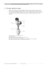
Page 3: ...well suited to dusty process conditions The device can operate at very low and very high process temperatures as long as the process connection temperature limits are observed 1 Optional touch screen...

Page 4: ...00 C 390 F and 40 bar 580 psig Measuring range up to 80 m 260 ft Antenna can be extended to suit any nozzle length PACTware and DTMs included as standard Optional second current output Directly access...

Page 5: ...es 2 antenna sizes DN80 or DN150 An installation wizard specifically for solids that permits the instrument to measure uneven surfaces accurately Antennas can be extended to suit any nozzle length Mad...

Page 6: ...f light in the gas above the product For further signal processing the difference f is calculated from the actual transmit frequency and the receive frequency The difference is directly proportional t...

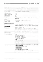
Page 7: ...sun cover 20 60 C 4 140 F if the ambient temperature is not in these limits the display switches off 2nd current output FOUNDATION Fieldbus output 4 wire device with local HART communication PROFIBUS...

Page 8: ...tes Drop antenna PTFE Drop antenna PTFE Drop antenna PTFE Drop antenna PTFE 50 150 C 58 300 F the process connection temperature must agree with the temperature limits of the gasket material Refer to...

Page 9: ...the sealed antenna extension option PTFE Drop antenna PTFE Drop antenna PTFE Drop antenna PTFE Drop antenna FKM FPM 40 150 C 40 300 F Kalrez 6375 20 150 C 4 300 F EPDM 50 C 150 C 58 300 F 1 PP Drop an...

Page 10: ...8 20 5 mA acc to NAMUR NE 43 3 Output signal Output 2 optional 4 20 mA no HART signal or 3 8 20 5 mA acc to NAMUR NE 43 Resolution 3 A Temperature drift Typically 25 ppm K Error signal High 22 mA Low...

Page 11: ...2 G 2 G Ex ia IIC T6 T3 II 1 D 1 2 D 2 D Ex iaD 20 or Ex iaD 20 21 or Ex iaD 21 IP6X T70 C T95 C II 1 2 G 2 G Ex d ia IIC T6 T3 II 1 2 D 2 D Ex tD iaD A21 20 or Ex tD iaD A21 IP6X T70 C T95 C IECEx IE...

Page 12: ...quipment and Telecommunications Terminal Equipment Directive 1999 5 EC in conjunction with ESTI EN 302 372 2006 FCC Rules Part 15 Industry Canada RSS 210 LVD Low Voltage Directive 2006 95 EC in conjun...

Page 13: ...raph of distance in m against r Figure 2 2 Selection of antenna for solid applications graph of distance in ft against r 1 Distance D m 2 Distance D ft 3 Dielectric constant r 4 On request 5 DN150 hor...

Page 14: ...3 Pressure temperature de rating EN 1092 1 flange and threaded connection in C and barg Figure 2 4 Pressure temperature de rating EN 1092 1 flange and threaded connections in F and psig 1 p barg 2 T...

Page 15: ...devices that are installed on a pressure vessel and used in Canada Figure 2 5 Pressure temperature de rating ASME B16 5 flange and threaded connections in C and barg Figure 2 6 Pressure temperature de...

Page 16: ...f g Housing 180 122 158 5 182 1 167 277 155 3 3 1 If fitted with standard cable glands Dimensions inches Weights lb a b c d e f g Housing 7 1 4 8 6 2 7 2 1 6 5 10 9 6 1 7 3 1 If fitted with standard...

Page 17: ...and weights in inches and lb Weather protection Figure 2 8 Dimensions of the weather protection option 1 Weather protection back view 2 Weather protection left side view Dimensions mm Weights kg a b c...

Page 18: ...m supplied with NPTF connection i Dimensions mm Weights kg a b c d e f h i Thread connection 182 1 167 201 250 496 49 246 2 75 6 8 Flange connection 182 1 167 201 263 480 62 217 2 75 11 1 18 9 1 If fi...

Page 19: ...supplied with NPTF connection Dimensions mm Weights kg a b c d e f h i Thread connection 182 1 167 201 250 565 49 315 2 95 7 2 Flange connection 182 1 167 201 263 549 62 286 2 95 11 6 28 2 1 If fitte...

Page 20: ...sions Figure 2 11 DN80 3 DN100 4 DN150 6 and DN200 8 sheet metal horn antenna versions 1 Sheet metal horn antenna DN80 3 DN100 4 DN150 6 or DN200 8 with G 1 or 1 NPT thread connection 2 Sheet metal ho...

Page 21: ...8 2 144 14 4 DN200 8 182 1 167 201 262 878 62 616 2 190 15 0 1 If fitted with standard cable glands 2 Additional antenna extensions of 39 length 105 mm are available Dimensions inches Weights lb a b c...

Page 22: ...connection with slanted flange option 182 1 167 201 246 383 45 137 2 74 10 2 6 4 26 6 Flange connection with flange plate protection option 182 1 167 201 246 383 45 137 74 39 6 6 26 8 1 If fitted wit...

Page 23: ...27 3 Flange connection with slanted flange option 182 1 167 201 246 460 45 214 2 144 10 2 8 1 27 9 Flange connection with flange plate protection option 182 1 167 201 246 460 45 214 144 39 1 If fitted...

Page 24: ...tion and agree with EN 50178 and IEC 60068 2 6 3 3 How to prepare the silo before you install the device 3 3 1 Theoretical data for nozzle position Obey the precautions that follow to make sure that t...

Page 25: ...all antennas For more data refer to Installation recommendations for solids on page 26 Do not put the device near to the product inlet If the product that enters the silo touches the antenna the devi...

Page 26: ...efer to the illustration that follows Figure 3 4 General installation recommendations 1 The level transmitter can continue to measure to the bottom of the silo if you tilt the device as shown in the i...

Page 27: ...et not supplied Nuts and bolts not supplied Wrench not supplied For more data refer to the handbook 3 5 2 How to install a device with a threaded connection Equipment needed Device Gasket for G 1 conn...

Page 28: ...devices used in hazardous areas additional safety notes apply please refer to the Ex documentation Observe without fail the local occupational health and safety regulations Any work done on the elect...

Page 29: ...HART communication 3 Output 1 14 30 VDC for an output of 22 mA at the terminal 4 Output 2 10 30 VDC for an output of 22 mA at the terminal For electrical data for device operation in hazardous locatio...

Page 30: ...delivered with the device or it can be downloaded free of charge from the website Downloadcenter 4 3 Protection category Make sure that the gaskets are not damaged Make sure that the electrical cables...

Page 31: ...drop network of up to 15 devices The device output is factory set to communicate point to point To change the communication mode from point to point point to point point to point point to point to mu...

Page 32: ...AVE 6300 R04 en 4 4 3 Multi drop networks Figure 4 5 Multi drop network non Ex 1 Address of the device n 1 for multidrop networks 2 Address of the device 1 for multidrop networks 3 4 mA HART 4 Resisto...

Page 33: ...vice 2 Junction box 3 H1 network 4 H1 HSE converter 5 High Speed Ethernet HSE 6 Workstation It is necessary to have a separate power supply to energize devices with the FOUNDATION Fieldbus output opti...

Page 34: ...bus line 6 Control system PLC Class 1 master device 7 Engineering or operator workstation Control tool Class 2 master device It is necessary to have a separate power supply to energize devices with th...

Page 35: ...glas FKM FPM 30 200 C Metaglas Kalrez 6375 20 200 C Metaglas EPDM 30 150 C Outputs 1 output 4 20 mA HART 2 outputs 4 20 mA HART 4 20 mA PROFIBUS PA 4 wire local HART FOUNDATION Fieldbus 4 wire local H...

Page 36: ...4 en 5 2 Rating data 5 3 Contact data Product name Operating pressure Rated pressure Process connection temperature Ambient temperature Dielectric constant Measurand level volume Silo height Comments...

Page 37: ...NOTES 6 37 OPTIWAVE 6300 C www krohne com 04 2011 4000305604 TD OPTIWAVE 6300 R04 en...

Page 38: ...6 NOTES 38 OPTIWAVE 6300 C www krohne com 04 2011 4000305604 TD OPTIWAVE 6300 R04 en...

Page 39: ...NOTES 6 39 OPTIWAVE 6300 C www krohne com 04 2011 4000305604 TD OPTIWAVE 6300 R04 en...

Page 40: ...roducts Measuring systems for the oil and gas industry Measuring systems for sea going tankers Head Office KROHNE Messtechnik GmbH Ludwig Krohne Str 5 D 47058 Duisburg Germany Tel 49 0 203 301 0 Fax 4...

Reviews: