background image

8

 TECHNICAL DATA 

114 

OPTIWAVE 7300 C

www.krohne.com

04/2010 - 4000172403 - HB OPTIWAVE 7300 R05 en

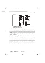
Dimensions and weights in mm and kg

Dimensions and weights in inches and lb

DN80/3

¨

 horn antenna versions

Figure 8-12: DN80/3

¨

 horn antenna versions

1  

DN80/3

¨

 horn antenna with G 1

½

 or 1

½

NPT thread connection

2  

DN80/3

¨

 horn antenna with flange connection

Dimensions [mm]

Weights 

[kg]

a

b

c

d

e

f

h

Øi

Thread 
connection

182 

 1

167

201

233

479

32

246 

 2

75

6.8

Flange 
connection

182 

 1

167

201

246 

 3

463 

 3

45 

 4

217 

 2

75

11.1...18.9

1

If fitted with standard cable glands

2

Additional antenna extensions of Ø39 × length 105 mm are available

3

With 

¼

NPTF purge connection option: add 17 mm to this dimension. With distance piece option: add 71 mm to this dimension.

4

#With 

¼

NPTF purge connection option: add 17 mm to this dimension. With distance piece option: add 71 mm to this dimension.

Dimensions [inches]

Weights 

[lb]

a

b

c

d

e

f

h

Øi

Thread 
connection

7.2 

 1

6.5

7.9

9.2

18.9

1.3

9.7 

 2

3

15

Flange 
connection

7.2 

 1

6.5

7.9

9.7 

 3

18.2

 3

1.8 

 3

8.5 

 2

3

24.4...41.5

1

If fitted with standard cable glands

2

Additional antenna extensions of Ø1.5 × length 4.1

¨

  are available

3

With 

¼

NPTF purge connection option: add 0.7

¨

 to this dimension. With distance piece option: add 2.8

¨

 to this dimension.

HB_OPTIWAVE7300_en_100430_4000172403_R05_D6B.book  Page 114  Thursday, May 6, 2010  6:14 PM

Summary of Contents for OPTIWAVE 7300 C

Page 1: ...me and mass measurement of liquids OPTIWAVE 7300 C OPTIWAVE 7300 C OPTIWAVE 7300 C OPTIWAVE 7300 C Handbook Handbook Handbook Handbook KROHNE 04 2010 4000172403 HB OPTIWAVE 7300 R05 en HB_OPTIWAVE7300...

Page 2: ...isation of KROHNE Messtechnik GmbH Subject to change without notice 2 OPTIWAVE 7300 C www krohne com 04 2010 4000172403 HB OPTIWAVE 7300 R05 en Copyright 2010 by KROHNE Messtechnik GmbH Ludwig Krohne...

Page 3: ...torage 17 3 3 Transport 18 3 4 Pre installation requirements 18 3 5 How to prepare the tank before you install the device 19 3 5 1 Pressure and temperature ranges 19 3 5 2 Theoretical data for nozzle...

Page 4: ...ith the AMS Device Manager 48 6 Operation 49 6 1 User modes 49 6 2 Operator mode 49 6 3 Supervisor mode 51 6 3 1 General notes 51 6 3 2 How to get access to the supervisor mode 51 6 3 3 Menu overview...

Page 5: ...ts availability 94 7 5 1 List of spare parts 94 7 5 2 List of accessories 96 7 6 Availability of services 97 7 7 Returning the device to the manufacturer 98 7 7 1 General information 98 7 7 2 Form for...

Page 6: ...2 372 2006 For more data refer to European Union EU on page 7 Low Voltage Directive 2006 95 EC in conjunction with EN 61010 1 2001 All devices are based on the CE marking and meet the requirements of...

Page 7: ...allation in closed metallic tanks It meets the requirements of the R TTE Radio Equipment and Telecommunications Terminal Equipment Directive 1999 05 EC for use in the member countries of the EU The de...

Page 8: ...mes street addresses or e mail addresses in the manufacturer s documents is always on a voluntary basis whenever possible Whenever feasible it is always possible to make use of the offerings and servi...

Page 9: ...implied warranties or the exclusion of limitation of certain damages you may if such law applies to you not be subject to some or all of the above disclaimer exclusions or limitations Any product pur...

Page 10: ...amage to the device it is essential that you read the information in this document and observe applicable national standards safety requirements and accident prevention regulations If this document is...

Page 11: ...en partial disregard of this warning can lead to serious health problems and even death There is also the risk of seriously damaging the device or parts of the operator s plant WARNING Disregarding th...

Page 12: ...k if you received completely all that you ordered Scope of delivery horn antenna Figure 2 1 Scope of delivery horn antenna 1 Signal converter and antenna in compact version 2 Antenna extensions option...

Page 13: ...enna extension 3 Quick Start 4 CD ROM including Handbook Quick Start Technical Datasheet and related software Scope of delivery hygienic antenna Figure 2 3 Scope of delivery hygienic antenna 1 Signal...

Page 14: ...a set up wizard fully potted electronic circuit boards and online help functions You usually will not need this Handbook to install set up and operate the device If it is ordered with the applicable...

Page 15: ...ameplate for more data refer to Non Ex nameplate on page 16 2 Process connection data size and pressure rating material reference and heat number 3 Gasket material data refer to the illustration that...

Page 16: ...nameplate Figure 2 6 Non Ex nameplate 1 Indicator arrow to cable entry cable entry size Notified body for radio approval 2 Nominal voltage for operation For further information refer to Non Ex on page...

Page 17: ...f you received completely all that you ordered INFORMATION Look at the device nameplate to ensure that the device is delivered according to your order Check for the correct supply voltage printed on t...

Page 18: ...cessory Do not subject the signal converter to heavy vibrations The devices are tested for vibration and agree with EN 50178 and IEC 60068 2 6 Figure 3 2 How to lift the device 1 Remove the converter...

Page 19: ...tically 3 Ambient temperature Non Ex devices 40 80 C 40 175 F Ex devices see supplementary operating instructions 4 Process pressure Depends on the antenna type Refer to the table that follows WARNING...

Page 20: ...imum distance of nozzle from the tank wall 1 7 tank height Maximum distance of nozzle from the tank wall 1 3 tank diameter 6 Minimum distance of nozzle from the tank wall 1 10 tank height Maximum dist...

Page 21: ...f the antenna easier attach the device to a short socket Figure 3 5 Product inlets 1 The device is in the correct position 2 The device is too near to the product inlet Figure 3 6 More than 1 FMCW rad...

Page 22: ...n empty spectrum scan for more data refer to How to use the empty spectrum function to filter parasite signals on page 76 or install a bypass chamber or stilling well 3 2 5 mm 0 1 max for high dielect...

Page 23: ...the standpipe must not be more than 5 mm 0 2 over the diameter of the antenna for a high dielectric constant liquid The standpipe must be straight There must be no sudden changes in internal diameter...

Page 24: ...s more than 1 liquid in the tank i These holes help the liquid to move freely between the stilling well and the tank Deburr the holes Stilling wells floating roofs If the device must be installed on a...

Page 25: ...ures correctly CAUTION If the device is installed in horizontal cylindrical tank that contains a high dielectric constant liquid without a stilling well do not put it on the tank centerline This will...

Page 26: ...id Additional process connections are necessary for the liquids to circulate freely along the length of the bypass chamber 3 7 How to install the device on the tank 3 7 1 How to install a device with...

Page 27: ...et correctly on the flange facing of the nozzle Lower the antenna carefully into the tank Tighten the flange bolts i Refer to local rules and regulations for the correct torque to apply to the bolts E...

Page 28: ...olts 3 7 2 How to install a device with a threaded connection Equipment needed Device Gasket for G 1 connection not supplied 50 mm 2 wrench not supplied If the process connection is larger than the an...

Page 29: ...op of the tank Lift the device a small distance Attach the antenna locking screw to the antenna extension Tighten the antenna locking screw Attach the device to the tank process connection Tighten the...

Page 30: ...ion BioControl Equipment needed Device Gasket Flange bolts not supplied Wrench not supplied How to attach a device with a Biocontrol connection Make sure the flange on the nozzle is level Make sure th...

Page 31: ...s level Make sure that you use the applicable gasket for the connection dimensions and the process Align the gasket correctly Lower the antenna carefully into the tank Attach the band clamp to the pro...

Page 32: ...antenna carefully into the tank Turn the nut on the device process connection to attach the device to the tank Tighten the connection i Refer to local rules and regulations for the correct torque to...

Page 33: ...pervisor Supervisor Supervisor Supervisor mode Go to Supervisor Advanced setup Installation Supervisor Advanced setup Installation Supervisor Advanced setup Installation Supervisor Advanced setup Inst...

Page 34: ...screen or HART communication PACTware Antenna extension antenna extension length number of extensions If you changed the antenna extension value in Supervisor Supervisor Supervisor Supervisor mode als...

Page 35: ...locking screw 1 with a 5 mm Allen wrench Lift the housing Tighten the housing locking screw 1 How to attach the signal converter Loosen the housing locking screw 1 with a 5 mm Allen wrench Attach the...

Page 36: ...110 Loosen the bracket nuts on the weather protection Remove the bracket Lower the weather protection onto the device Turn the weather protection so that the keyhole points forward Attach the bracket...

Page 37: ...ewdriver into the keyhole at the front of the weather protection Turn the screwdriver counterclockwise Pull the top of weather protection up and forward i This will open the weather protection Figure...

Page 38: ...Observe without fail the local occupational health and safety regulations Any work done on the electrical components of the measuring device may only be carried out by properly trained specialists IN...

Page 39: ...tput 2 Figure 4 2 Electrical connections for non Ex devices 1 Power supply 2 Resistor for HART communication 3 Output 1 14 30 VDC for an output of 22 mA at the terminal 4 Output 2 10 30 VDC for an out...

Page 40: ...ree of charge from the website Downloadcenter 4 3 Protection category Make sure that the gaskets are not damaged Make sure that the electrical cables are not damaged Make sure that the electrical cabl...

Page 41: ...ice output is factory set to communicate point to point To change the communication mode from point to point point to point point to point point to point to multi drop multi drop multi drop multi drop...

Page 42: ...igure 4 5 Multi drop network non Ex 1 Address of the device n 1 for multidrop networks 2 Address of the device 1 for multidrop networks 3 4 mA HART 4 Resistor for HART communication 5 Power supply 6 H...

Page 43: ...hernet HSE 6 Workstation INFORMATION It is necessary to have a separate power supply to energize devices with the FOUNDATION Fieldbus output option 4 wire device with local HART connection The FF FF F...

Page 44: ...g or operator workstation Control tool Class 2 master device INFORMATION It is necessary to have a separate power supply to energize devices with the PROFIBUS PA output option 4 wire device with local...

Page 45: ...ting concept You can read measurements and configure the device with A digital display screen optional A connection to a system or PC with PACTware You can download the Device Type Manager DTM file fr...

Page 46: ...conds a help message is displayed This will explain what the menu is and what the parameters do Press and U Esc at the same time to go back to the menu If you do not touch the display for another 30 s...

Page 47: ...ication standard for sending information between the system and the field device This standard agrees with IEC PAS 62453 Field devices are easily integrated Installation is supported by a user friendl...

Page 48: ...e and read process data Store and read diagnostic status information Help plan preventive maintenance to reduce a plant s downtime to a minimum The DD file is given on the CD ROM supplied with the dev...

Page 49: ...y the supervisor as described below Functions of kepypad buttons in operator mode Keypad button Description Normal function Hotkey function Right Change display style 1 Enter program mode 2 Enter Down...

Page 50: ...V V U V Back to the top of the list Back to the top of the list Reflectivity U V Signal screen 3 V Back to the top of the list 1 This data is only available if you created a volume table Refer to the...

Page 51: ...menu For more data refer to Function description on page 56 Table B Test 6 3 2 How to get access to the supervisor mode Do the steps that follow Press the button for one second i This displays the lo...

Page 52: ...ck Link 2 default Measurement Quality A 4 Quick Link 3 default Language A 5 Quick Link 4 default Length Unit A 6 Quick Link 5 default Display Mode B Test B 1 Test B 2 Information C Advanced Setup C 1...

Page 53: ...d buttons in the menu lists Menu navigation Figure 6 1 Menu navigation 1 Menu selection bar 2 Header bar 3 Menu list 4 Menu item that is not available in grey text Keypad button Description Function R...

Page 54: ...Lists of parameters in menu items Figure 6 2 Lists of parameters in menu items 1 Parameter selection bar 2 Menu name 3 Parameter used at this time Keypad button Description Function Right Enter Select...

Page 55: ...es in menu items 1 Maximum value 2 Minimum value 3 Cursor on the digit to be changed 4 Menu name 5 Illustration of menu item 6 Error message Keypad button Description Function Right Move the cursor to...

Page 56: ...ink 1 Enter Down Up Screen displays information in English 2 Esc Escape Go back to the operator mode 1 Make a selection from the Advanced Setup menu list 2 Press this button for 3 seconds Menu No Step...

Page 57: ...l Step 4 is available if you set Stillwell in step 3 min max 8 200 mm 0 31 7 88 100 mm 3 94 4B Stillwell Height The height of the stillwell Step 4 is available if you set Stillwell in step 3 min max 0...

Page 58: ...ntents Save Cancel 3 Save A 1 4 Conversion Follow this procedure to set the device up to display readings in volume mass or user defined units Submenu Conversion submenu Volume Volume Volume Volume 1...

Page 59: ...e values automatically supplied by the device Submenu Conversion submenu Free Unit Free Unit Free Unit Free Unit If you cannot find the units or tank shape in the menu you can customize the conversion...

Page 60: ...tput current stays at the value where the error occurred Hold Hold Hold Hold is not available if 3 8 20 5 mA NAMUR is the output range 3 6 mA 22 mA Hold 4 20 mA range only 22 mA 6 Output 1 HART HART A...

Page 61: ...nu and press for 1 second You can store up to 5 functions in this way Measure ment Quality A 4 Quick Link 3 Direct link to an item in the Advanced Setup menu Go to a function in the Advanced Setup men...

Page 62: ...put settings This includes assigned functions 4 20 mA scale settings error handling and HART parameters Read only B 2 2 15 Min Log A log of output values for the last 15 minutes A log is taken every 1...

Page 63: ...on Type The installation on the tank for the device Metal Tank Plastic Tank Free Air Application Metal Tank C 1 2 Tank Height Measuring Range Tank height is the distance from the tank connecting flang...

Page 64: ...device continues to display the blocking distance min max 0 220 m tank height 0 72 ft tank height 0 3 m 1 ft C 1 10 Reference Offset Offset relating to a reference location distance This value is pos...

Page 65: ...m min 1 64 ft min C 1 16 Multiple Reflections Multiple reflections will cause the device to display smaller readings Objects in the tank sharp corners installation of the device on a large nozzle or a...

Page 66: ...displayed in the operator mode Level Distance Volume Mass Ullage Volume Ullage Mass Reflection Level C 3 2 4 mA Setting Give a measurement value to 4 mA min max 1 0 m 0 ft C 3 3 20 mA Setting Give a m...

Page 67: ...ation you need refer to these menu items C 5 1 1 Language Information can be displayed in any of the 9 languages stored in the device If it is necessary to change the display quickly to English press...

Page 68: ...new password To confirm the change enter the new password a second time VU C 6 Reset To reset the device to default settings refer to these menu items C 6 2 Clear Error Record Erase the error record i...

Page 69: ...vel 4 mA Setting for Level Tank Height TBO RO 1 Tank height TBO BD 2 Volume 4 mA Setting for Volume Max value in the volume table Max value in the volume table Mass 4 mA Setting for Mass Max value in...

Page 70: ...rvisor Advanced setup Device setup Passwords Supervisor Supervisor Advanced setup Device setup Passwords Supervisor Supervisor Advanced setup Device setup Passwords Supervisor Type in the new 6 charac...

Page 71: ...nt output is set to 4 mA This value does not change in multidrop mode How to change from multidrop to point to point mode Enter supervisor mode Go to Advanced Setup Output 1 HART HART Address Advanced...

Page 72: ...ted Press Press and U Esc at the same time to exit to the save settings window Select Save Save Save Save and press i The device will go back to operator mode 6 4 5 Distance measurement The device dis...

Page 73: ...nce point from which level is measured Use this menu item Tank Bottom Offset C 1 11 Figure 6 5 Distance measurement 1 Tank Height C 1 2 2 Reference Offset C 1 10 3 Blocking Distance C 1 9 4 4 mA Setti...

Page 74: ...mode Conversion Supervisor Quick setup Setup mode Conversion Supervisor Quick setup Setup mode Conversion Supervisor Quick setup Setup mode Conversion Complete all the steps in the set up procedure T...

Page 75: ...setup procedure INFORMATION When you create a table get more conversion data for parts of the tank where there are Surfaces with curves Sudden changes in the cross section This will make volume measur...

Page 76: ...o you want to use the average value or the maximum value Select Average Average Average Average or Maximum Maximum Maximum Maximum and then press i Use the maximum for tanks that have moving parts Use...

Page 77: ...move the cursor to the reflection with the largest amplitude given in dB Make a note of the distance of the reflection measured by the device i The distance to the reflection will be the new tank hei...

Page 78: ...tank bottom reflection 1 Tank bottom offset menu item C 1 11 2 Tank height menu item C 1 2 3 Signal amplitude in dB 4 True position of the tank bottom 5 Offset position of the tank bottom 6 Distance...

Page 79: ...senses an error condition it displays an error symbol in the top left corner of the display screen Enter the supervisor mode to either Do an error status check or Read the error records and get more...

Page 80: ...nt Quality Test Information Measurement Quality i This shows the status of device errors at this time A tick symbol next to an error in the list shows that this error is active and may have an unwante...

Page 81: ...s Test Information Error Records Test Information Error Records Test Information Error Records Use V V V V and U U U U to scroll the error list There are 5 error messages per page Figure 6 12 Error re...

Page 82: ...device is switched back on The error symbol is no longer displayed after you read the error record 6 6 2 Error handling Types of error message Figure 6 13 Description of the error 1 Description of the...

Page 83: ...the supplier Self test manager Self Test has failed E The device s self test failed This can occur if the ambient temperature is not between 40 80 C 40 175 F Energize the device when the ambient tempe...

Page 84: ...ues contact the supplier or replace the electronics block For more data refer to Replacement of the complete electonic module on page 90 Peak and spectrum Spectrum quality is bad W The quality of the...

Page 85: ...d the process Reconfigure the device and record a new empty spectrum Follow the instructions on page 76 If necessary contact the supplier Software error Unable to load DSP firmware E The DSP Firmware...

Page 86: ...e terminal compartment cover clean If dirt collects on the device clean it Wipe the plastic sun cover with a damp cloth WARNING Do not let more than 5 mm 0 2 of dust collect on the top surface of the...

Page 87: ...lange system under process conditions Use only authorized service staff to repair the device WARNING Purge the antenna with a dry gas or liquid that is applicable to the process CAUTION Purge the ante...

Page 88: ...www krohne com 04 2010 4000172403 HB OPTIWAVE 7300 R05 en 7 4 2 Replacement of the display cover Figure 7 1 Removal of the device display cover HB_OPTIWAVE7300_en_100430_4000172403_R05_D6B book Page 8...

Page 89: ...rews that keep the display attached to the housing 5 Keep the remaining assembly and put it into storage Make sure that the top of the housing has a protective cover 6 Send the display to an authorize...

Page 90: ...e com 04 2010 4000172403 HB OPTIWAVE 7300 R05 en 7 4 3 Replacement of the complete electonic module Figure 7 2 Removal of the complete electronic module HB_OPTIWAVE7300_en_100430_4000172403_R05_D6B bo...

Page 91: ...into 2 pieces It is then difficult to remove these pieces from the housing 5 Remove the back end and microwave unit from the housing Send the electronics block to an authorized agent for maintenance...

Page 92: ...www krohne com 04 2010 4000172403 HB OPTIWAVE 7300 R05 en 7 4 4 Replacement of the terminal module Figure 7 3 Removal of the terminal module HB_OPTIWAVE7300_en_100430_4000172403_R05_D6B book Page 92...

Page 93: ...Send it to an authorized agent for maintenance How to attach the terminal module Connect the wire connector to the terminal module Push the wires into the slot below the connector on the terminal blo...

Page 94: ...e for a period of 3 years after delivery of the last production run for the device This regulation only applies to spare parts which are under normal operating conditions subjects to wear and tear 7 5...

Page 95: ...0 Terminal module with 1 output NEPSI Ex dia 1 XF704F0000000E1000 Terminal module with 2 outputs non Ex 1 XF7040000000032000 Terminal module with 2 outputs ATEx Ex ia 1 XF7042000000032000 Terminal mod...

Page 96: ...6 OPTIWAVE 7300 C www krohne com 04 2010 4000172403 HB OPTIWAVE 7300 R05 en 7 5 2 List of accessories Figure 7 5 Accessories HB_OPTIWAVE7300_en_100430_4000172403_R05_D6B book Page 96 Thursday May 6 20...

Page 97: ...rotection 1 XF7040000000000001 3 Blind cover with a gasket and screws 1 XF704000000000000B Gasket for the blind cover 1 F3177420000 Hinge screws for the blind cover 2 F3177340000 Lock screw for the bl...

Page 98: ...personnel manufacturer may only handle test and repair returned devices that have been in contact with products without risk to personnel and environment This means that the manufacturer can only serv...

Page 99: ...hazardous toxic caustic flammable We checked that all cavities in the device are free from such substances We have flushed out and neutralized all cavities in the device We hereby confirm that there i...

Page 100: ...For further signal processing the difference f is calculated from the actual transmit frequency and the receive frequency The difference is directly proportional to the distance A large frequency diff...

Page 101: ...output FOUNDATION Fieldbus output 4 wire device with local HART communication PROFIBUS PA output 4 wire device with local HART communication PTFE PP flange plate protection for Drop antennas without...

Page 102: ...st agree with the temperature limits of the gasket material Refer to Materials in this table Ex see supplementary operating instructions or approval certificates Drop antenna PP Drop antenna PP Drop a...

Page 103: ...s fitting Standard for Horn and Drop antennas Stainless steel 1 4404 316L a PP or PTFE flange plate protection option is also available for the Drop antenna Standard for Hygienic antennas PEEK Option...

Page 104: ...Not for stainless steel housings M25 1 5 for stainless steel housings only Cable gland Standard none Options M20 1 5 for non Ex and Ex approved devices with M20 1 5 and M25 1 5 cable entries others ar...

Page 105: ...device fulfils the statutory requirements of the EC directives The manufacturer certifies successful testing of the product by applying the CE mark Explosion protection Explosion protection Explosion...

Page 106: ...1 2006 R TTE Radio Equipment and Telecommunications Terminal Equipment Directive 1999 5 EC in conjunction with ESTI EN 302 372 2006 FCC Rules Part 15 Industry Canada RSS 210 LVD Low Voltage Directive...

Page 107: ...antenna for liquid applications graph of distance in ft against r 1 Distance D m 2 Distance D ft 3 Dielectric constant r range for storage stillwell applications 4 Dielectric constant r range for proc...

Page 108: ...d barg Figure 8 5 Pressure temperature de rating EN 1092 1 flange and threaded connections in F and psig 1 p barg 2 T C 3 p psig 4 T F 5 Threaded connection G ISO 228 1 6 Flange connection PN100 7 Fla...

Page 109: ...nnections in F and psig 1 p barg 2 T C 3 p psig 4 T F 5 Flange connection Class 900 and Class 1500 Threaded connection NPT ASME B1 20 1 6 Flange connection Class 600 7 Flange connection Class 300 8 Fl...

Page 110: ...3 1 If fitted with standard cable glands Dimensions inches Weights lb a b c d e f g Housing 7 1 4 8 6 2 7 2 1 6 5 10 9 6 1 7 3 1 If fitted with standard cable glands CAUTION Cable glands are delivered...

Page 111: ...tion Figure 8 9 Dimensions of the weather protection option 1 Weather protection back view 2 Weather protection left side view Dimensions mm Weights kg a b c d Weather protection 208 231 5 268 1 66 2...

Page 112: ...6 14 1 1 If fitted with standard cable glands 2 Additional antenna extensions of 39 length 105 mm are available 3 With NPTF purge connection option add 17 mm to this dimension With distance piece opti...

Page 113: ...1 If fitted with standard cable glands 2 Additional antenna extensions of 39 length 105 mm are available 3 With NPTF purge connection option add 17 mm to this dimension With distance piece option add...

Page 114: ...tenna extensions of 39 length 105 mm are available 3 With NPTF purge connection option add 17 mm to this dimension With distance piece option add 71 mm to this dimension 4 With NPTF purge connection o...

Page 115: ...2 1 If fitted with standard cable glands 2 Additional antenna extensions of 39 length 105 mm are available 3 With NPTF purge connection option add 17 mm to this dimension With distance piece option a...

Page 116: ...6 3 26 Flange connection with flange plate protection option 182 1 167 201 246 383 45 137 74 39 6 6 26 8 1 If fitted with standard cable glands 2 Additional antenna extensions of 39 length 105 mm are...

Page 117: ...0 2 Hygienic antenna with SMS connection Dimensions mm Weights kg a b d h DIN 11851 connection 182 1 167 264 8 3 8 Tri Clamp connection 182 1 167 264 8 3 7 Neumo BioControl connection 182 1 167 247 25...

Page 118: ...OFIBUS PA 4 wire local HART FOUNDATION Fieldbus 4 wire local HART Display Without With Specify language Approvals No Ex ATEX Ex ia ATEX Ex d ia WHG 4 FM IS Class 1 Div 1 Dual Seal FM XP IS Class 1 Div...

Page 119: ...the level 1 product or the surface of the top product 2 or more products See the diagrams at the end of this section Drop antenna Drop antenna Drop antenna Drop antenna A new generation of antenna mad...

Page 120: ...ference signals False radar reflections Level Level Level Level Height from the bottom of the tank user defined to the surface of the top product Tank height distance See the diagrams at the end of th...

Page 121: ...tank contents Ullage volume Ullage volume Ullage volume Ullage volume Unfilled volume See the diagrams at the end of this section Volume Volume Volume Volume Total volume of tank contents Waveguide W...

Page 122: ...VE 7300 C www krohne com 04 2010 4000172403 HB OPTIWAVE 7300 R05 en Figure 9 2 Measurement definitions level 1 Level 2 Volume or mass HB_OPTIWAVE7300_en_100430_4000172403_R05_D6B book Page 122 Thursda...

Page 123: ...NOTES 10 123 OPTIWAVE 7300 C www krohne com 04 2010 4000172403 HB OPTIWAVE 7300 R05 en Notes HB_OPTIWAVE7300_en_100430_4000172403_R05_D6B book Page 123 Thursday May 6 2010 6 14 PM...

Page 124: ...d gas industry Measuring systems for sea going tankers Head Office KROHNE Messtechnik GmbH Ludwig Krohne Str 5 D 47058 Duisburg Germany Tel 49 0 203 301 0 Fax 49 0 203 301 10389 info krohne de KROHNE...

Reviews: