4
ELECTRICAL CONNECTIONS
44
OPTIWAVE 7300 C
www.krohne.com
04/2010 - 4000172403 - HB OPTIWAVE 7300 R05 en
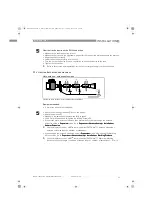
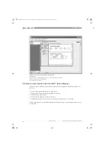
Figure 4-7: PROFIBUS PA/DP network (non-Ex)
1
Field device
2
Bus termination
3
PROFIBUS PA bus segment
4
Segment coupler (PA/DP link)
5
PROFIBUS DP bus line
6
Control system (PLC / Class 1 master device)
7
Engineering or operator workstation (Control tool / Class 2 master device)
INFORMATION!
It is necessary to have a separate power supply to energize devices with the PROFIBUS PA
output option (4-wire device with local HART
®
connection). The PROFIBUS PA
PROFIBUS PA
PROFIBUS PA
PROFIBUS PA terminal is
connected to a segment coupler. The 24 VDC
24 VDC
24 VDC
24 VDC terminal energizes the device. The power supply is
not shown in the illustration.
HB_OPTIWAVE7300_en_100430_4000172403_R05_D6B.book Page 44 Thursday, May 6, 2010 6:14 PM

