ELECTRICAL CONNECTIONS
3
27
OPTIWAVE 7300 C
www.krohne.com
04/2009 - 4000050002 - QS OPTIWAVE 7300 R05 en
Electrical connections
3.1 Safety instructions
3.2 Electrical installation: outputs 1 and 2
DANGER!
All work on the electrical connections may only be carried out with the power disconnected. Take
note of the voltage data on the nameplate!
DANGER!
Observe the national regulations for electrical installations!
DANGER!
For devices used in hazardous areas, additional safety notes apply; please refer to the Ex
documentation.
WARNING!
Observe without fail the local occupational health and safety regulations. Any work done on the
electrical components of the measuring device may only be carried out by properly trained
specialists.
INFORMATION!
Look at the device nameplate to ensure that the device is delivered according to your order.
Check for the correct supply voltage printed on the nameplate.
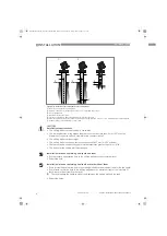
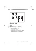
Figure 3-1: Electrical installation
1
Terminal compartment cover
2
Output 1: current output -
3
Output 1: current
4
Grounding terminal in the housing
5
Output 2: current output -
6
Output 2: current
7
Grounding terminal between the process connection and the converter
INFORMATION!
Output 1 energizes the device and is used for HART
®
communication. If the device has the
second current output option, use a separate power supply to energize output 2.
QS_OPTIWAVE7300_en_090528_4000050002_R05_web.book Page 27 Friday, May 29, 2009 4:01 PM


