background image

 ELECTRICAL CONNECTIONS 

4

11

SMARTPAT COND 5200

www.krohne.com

03/2022 - 4004007703 - MA SMARTPAT COND 5200 R03 en

4.1  General notes

In order to avoid risks, always observe the following points when electrically connecting a 

sensor:

Ensure that all connecting cables conform to the valid installation standards (e.g. IEC 60079-

14) and withstand the maximum operating temperature.

Securely lay the connecting cables and sufficiently protect them against damage.

Securely connect all the cores not in use with the ground potential of the explosive area or 

carefully insulate them from each other and from ground (test voltage 

 500V

eff

).

4.2  Power supply

The sensor does not require a separate power supply. The required supply for the electronics is 

provided via the 4...20 mA current output.

4.3  Inputs/outputs

The connector pin assignment of the sensor is described in the standard documentation. The 

signal circuits of the sensor may only be connected to certified intrinsically safe slave units or 

circuits. For more information refer to chapter "Electrical data".

INFORMATION!

When connecting the sensor cable, observe the standard documentation for the sensor, the 

chapter "Installation" .

When using junction box SJB 200 W-Ex, the corresponding handbook must also be observed.

Summary of Contents for SMARTPAT COND 5200

Page 1: ...Digital conductivity sensor Category II 1 G EPL Ga SMARTPAT COND 5200 Supplementary Instructions KROHNE 03 2022 4004007703 MA SMARTPAT COND 5200 R03 en AD ...

Page 2: ... 6 2 3 Flammable products 7 2 4 Device category 7 2 5 Protection type for gas hazardous areas 8 2 6 Temperature classes 8 2 7 Electrical data 9 3 Installation 10 3 1 Installation 10 3 2 Specific conditions of use 10 4 Electrical connections 11 4 1 General notes 11 4 2 Power supply 11 4 3 Inputs outputs 11 4 4 Grounding and equipotential bonding 12 5 Operation 13 5 1 Starting up for the first time ...

Page 3: ...eclaration of conformity on his own responsibility conformity with the protection goals of directive 2014 34 EU for use in hazardous areas with gas Conformity with harmonised standards was checked by a notified body in accordance with EN IEC 60079 0 2018 and EN 60079 11 2012 The EC declaration of conformity is based on the EC type examination certificate You can download the EC type examination ce...

Page 4: ...h EN IEC 60079 0 2018 and EN 60079 11 2012 by an UK Approved Body The UK declaration of conformity is based on the UK type examination certificate issued by CSA Group If necessary the UK type examination certificate can be downloaded from the manufacturer s website 1 5 Safety instructions Assembly installation start up and maintenance may only be performed by personnel trained in explosion protect...

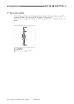
Page 5: ...e of the sensor is the measurement of conductivity in conductive liquids It has a connection for a 4 20 mA current output with HART communication The connection is designed as a plug connector and at the same time supplies the sensor with power 1 VP 2 0 connector 2 PEEK housing 3 G3 4 A thread male or 3 4 14 NPT male 4 Electrodes graphite PES ...

Page 6: ...urer 2 Device name 3 Cell constant 4 TAG number 5 Order code 6 Serial number D14xxxxxxx Year of manufacture 2014 7 Ex data acc to KIWA 14ATEX0002 X or IECEx KIWA 14 0004X or CSAE 21UKEX2617X 8 Manufacturing date Ingress protection 9 Observe the installation and operating instructions SMARTPAT COND 5200 KIWA 14ATEX0002 X Ex ia IIC T6 T4 Ga SN D14xxxxxxx 0102 VGS C 1234567 II1G TAG ABCD1234 c 1 ER 1...

Page 7: ...losion protection may not be applicable for the sensor part piping 2 4 Device category The sensor is designed in category II 1 G for use in zone 0 For more information refer to chapter Flammable products DANGER Operation with flammable products is only permitted as long as no explosive fuel air mixture builds up inside of the piping at the same time the atmospheric conditions are exceeded The oper...

Page 8: ... heat radiation e g direct sunlight adjoining hot parts Insulation does not obstruct the ventilation of the sensor Components of the Ex marking and their definition II Group II explosion protection 1 Equipment category 1 G Gas explosion protection Ex ia Intrinsically safe equipment protection level ia IIC Gas groups IIA IIB IIC approved T6 T4 Temperature class range T6 T4 Ga EPL Ga approved suitab...

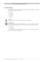
Page 9: ...mA Pi 1 0 W Li 10 µH Ci 5 nF CAUTION Capacity and inductance of the connecting cable have to be considered INFORMATION For information about rated data and the HART interface consult the standard documentation The internal intrinsically safe electrode circuit is limited to the following maximum values Uo 7 8 V Io 15 5 mA Po 30 5 mW The connections for the intrinsically safe 4 20 mA sensor circuit ...

Page 10: ...may only be cleaned with a wet cloth DANGER The manufacturer is not liable for any damage or injuries resulting from improper use or use other than the intended purpose This applies in particular to hazards due to insufficient corrosion resistance and suitability of the materials in contact with product DANGER Installation and setup must be carried out according to the applicable installation stan...

Page 11: ... explosive area or carefully insulate them from each other and from ground test voltage 500Veff 4 2 Power supply The sensor does not require a separate power supply The required supply for the electronics is provided via the 4 20 mA current output 4 3 Inputs outputs The connector pin assignment of the sensor is described in the standard documentation The signal circuits of the sensor may only be c...

Page 12: ...IEC 60079 14 When using junction box type SJB 200 W Ex the shield of the sensor cable must be connected to the shield connector provided This will ensure sufficient electrostatic grounding and at the same time prevent unacceptably high equalizing currents INFORMATION The connections for the intrinsically safe 4 20 mA sensor circuit are galvanically isolated from both the electrode circuit and the ...

Page 13: ...able them during operation Include the sensor in the periodic pressure tests of the plant when operating with flammable products 5 3 Electrostatic charge In order to avoid ignition hazards due to electrostatic charge the sensors may not be used in areas where processes that generate strong charges mechanical friction and cutting processes spraying of electrons e g in the vicinity of electrostatic ...

Page 14: ...smantling the electrical connecting lines of the device ensure that all the cables leading to the sensor are de energized themselves and to the reference potential of the explosive area All the relevant process pipes or containers must be depressurized before dismounting the sensor If the process pipes or the container contain products that are harmful to the environment or to health implement the...

Page 15: ...NOTES 7 15 SMARTPAT COND 5200 www krohne com 03 2022 4004007703 MA SMARTPAT COND 5200 R03 en ...

Page 16: ...solutions Engineering commissioning calibration maintenance and training services Head Office KROHNE Messtechnik GmbH Ludwig Krohne Str 5 47058 Duisburg Germany Tel 49 203 301 0 Fax 49 203 301 10389 info krohne de KROHNE 03 2022 4004007703 MA SMARTPAT COND 5200 R03 en AD Subject to change without notice The current list of all KROHNE contacts and addresses can be found at www krohne com ...

Reviews: