background image

15

6 Setup with the integrated display and adjustment unit

SU 600 • 4 … 20 mA signal conditioning instrument

30652-EN-150129

measuring transducers without separate operating voltage (sensor 

in two-wire version).

• 

In passive mode, the sensors are not powered, only the measure-

ment value is transmitted. This mode is provided for connection of 

transmitters with their own separate operating voltage (sensors in 

four-wire version).

→ 

Set the function switch to position [

F

] and select the suitable 

mode with the [

+/-

] keys. Save your settings by pushing both keys 

simultaneously.

When a pressure transmitter is used, an offset correction should be 

carried out first. These instruments are factory-set in a certain posi

-

tion. If the pressure transmitter is now mounted in a different position, 

its measuring range is shifted slightly. The zero point is readjusted by 

carrying out the offset correction in uncovered (unpressurised) condi

-

tion. The complete measuring range will be shifted by the deviating 

amount.
1.  Make sure that the pressure transmitter is completely unpressur-

ised, uncovered (unimmersed) and mounted in its final position.

2.  Set the function switch to position [

A

 ]. The display indicates now 

the actual sensor current in mA. Save the current status by push-

ing the [

+/-

 ] keys simultaneously.

For this adjustment procedure, two sensor current values 

(4 … 20 mA) must be entered corresponding to the levels 0 % and 

100 %.

When using a pressure transmitter, an offset correction should be car

-

ried out to reach maximum accuracy. Carry out this offset correction 

before adjustment and with the sensor uncovered (unimmersed).

→ 

Now select the position [

D

] or [

E

] on the function switch, enter the 

current values in mA for min. or max. adjustment and save your 

settings.

During this adjustment procedure, the current level is assigned to 

a certain percentage value. For this reason, percentage values that 

correspond to the actual filling levels must be entered for the min. and 

max. adjustment. The ideal calibration is at 0 % and 100 %. Because 

it is not always possible to empty or fill a vessel completely, any value 

can of course be entered. The greater the difference between the two 

adjustment points, the more precise the measurement. It does not 

matter which value is entered first.

→ 

Select position [

B

] or [

C

] on the function switch, enter the per-

centage values for the min. and max. adjustment and save your 

settings.

Two operating relays are integrated inSU 600 for level detection. First 

of all, determine at which switching points the relays should switch on 

and off again. Furthermore you have to distinguish between the relay 

modes overfill and dry run protection. You switch over by exchanging 

the ON/OFF values of the relay.

Offset correction

Adjustment in mA without 

changing the level

Adjustment in % by 

changing the level

Relay outputs

Summary of Contents for SU 600

Page 1: ...Operating Instructions SU 600 4 20 mA signal conditioning instrument Document ID 30652...

Page 2: ...ion 7 3 3 Operation 7 3 4 Packaging transport and storage 7 4 Mounting 4 1 General instructions 9 4 2 Mounting instructions 9 5 Connecting to power supply 5 1 Preparing the connection 11 5 2 Input mod...

Page 3: ...ip note This symbol indicates helpful additional information Caution If this warning is ignored faults or malfunctions can result Warning If this warning is ignored injury to persons and or serious da...

Page 4: ...3 Warning about incorrect use Inappropriate or incorrect use of the instrument can give rise to application specific hazards e g vessel overfill or damage to system components through incorrect mount...

Page 5: ...we confirm successful testing of the product 2 7 Environmental instructions Protection of the environment is one of our most important duties That is why we have introduced an environment management...

Page 6: ...instructions manual F E D C B A987 6 5 4 3 2 1 0 1 2 1 3 7 6 5 2 4 Fig 1 SU 600 1 Status indication operating relay 1 and 2 2 Status indication fail safe relay 3 Status indication operation 4 adjustm...

Page 7: ...U 600 is carried out via the integrated keys and a 16 step function switch 3 4 Packaging transport and storage Your instrument was protected by packaging during transport Its capacity to handle normal...

Page 8: ...A signal conditioning instrument 30652 EN 150129 Avoiding mechanical shock and vibration Storage and transport temperature see chapter Supplement Technical data Ambient conditions Relative humidity 20...

Page 9: ...ounted via the screws or carrier rail it must always be inside a switching cabinet or protective case 4 2 Mounting instructions 1 Make sure that the cutout required for installation has a size of 92 x...

Page 10: ...the adapter plate 1 to the rear of SU 600 spring of the adapter plate downward and fasten the plate with screw 2 M4 x 6 2 PlaceSU 600 against the carrier rail 3 from below and push the instrument upw...

Page 11: ...side of SU 600 must be made via a ceramic capacitor e g 1 nF 1500 V The low frequency potential equalisation currents are thus suppressed but the protective effect against high frequency interference...

Page 12: ...ect power supply switched off to terminal 5 and 6 4 If necessary connect fail safe and operating relay as well as cur rent output The electrical connection is finished 5 4 Wiring plan 1 2 3 4 18 17 16...

Page 13: ...witch as well as two keys To open the cover insert a screwdriver in the two slots on the top and turn it slightly F E D C B A987 6 5 4 3 2 1 0 1 2 1 3 7 6 5 2 4 Fig 6 Display and adjustment elements 1...

Page 14: ...on The output signal jumps briefly to the set fault value Then the actual measured value is displayed and the corresponding current is transmitted to the current output The measured value indication s...

Page 15: ...ocedure two sensor current values 4 20 mA must be entered corresponding to the levels 0 and 100 When using a pressure transmitter an offset correction should be car ried out to reach maximum accuracy...

Page 16: ...o adjust the on and off switching points of relay 1 set the func tion switch to position 1 or 2 enter the switching points for ON or OFF and save your settings If necessary proceed in the same way wit...

Page 17: ...ulation mode can be used Any individual measured value can be simulated and e g the correct behaviour of the relays and the connected instruments can be checked Switching over between the functions OP...

Page 18: ...t the function switch to position 8 Select with the keys the measured value output 4 20 mA or 0 20 mA For this example choose 4 20 The displayed numbers have the following meanings 0 20 0 20 mA 4 20 4...

Page 19: ...when the relay is energized If the switch ing points are too close together 0 1 the appropriate LED flashes The relay takes on the safe condition In mode OPERATE an error message is outputted on the d...

Page 20: ...adjustment are checked for plausibility If irregularities occur or in case of incorrect parameter adjustment a fault signal is triggered In case of an instrument defect or line break shortcircuit a f...

Page 21: ...be carried out again 7 3 Instrument repair If a repair is necessary please proceed as follows On our homepage in the Internet under http www krohne mar com fileadmin media lounge PDF Download Specimen...

Page 22: ...separable WEEE directive 2002 96 EG This instrument is not subject to the WEEE directive 2002 96 EG and the respective national laws Pass the instrument directly on to a spe cialised recycling company...

Page 23: ...ensor supply through SU 600 mode passive Sensor has an own power supply Measured value transmission 4 20 mA Deviation Accuracy 20 A 0 1 of 20 mA Terminal voltage mode active 30 22 V at 4 20 mA Current...

Page 24: ...relay 1 2 2 x LED yellow Operation Adjustment elements 2 x key 1 x function selection switch Ambient conditions Ambient temperature 20 60 C 4 140 F Storage and transport temperature 40 80 C 40 176 F E...

Page 25: ...ent 30652 EN 150129 Galvanic separation between relay output and digital part Reference voltage 250 V Voltage resistance of the isolation 4 kV 9 2 Dimensions on 1 2 1 2 69 mm 2 72 2 mm 0 08 19 mm 0 75...

Page 26: ...26 9 Supplement SU 600 4 20 mA signal conditioning instrument 30652 EN 150129 9 3 Certificate 9 3 CE declarations of conformity...

Page 27: ...27 9 Supplement SU 600 4 20 mA signal conditioning instrument 30652 EN 150129 Fig 9 CE declarations of conformity...

Page 28: ...28 9 Supplement SU 600 4 20 mA signal conditioning instrument 30652 EN 150129 9 4 Trademark All the brands as well as trade and company names used are property of their lawful proprietor originator...

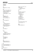
Page 29: ...g 9 Function switch 14 G Grounding 11 I Input active 11 Passive 11 Installation possibilities 9 Integration time 14 17 L LC display 24 Line break 20 Load 24 O Offset correction 15 Overflow protection...

Page 30: ...30 Notes SU 600 4 20 mA signal conditioning instrument 30652 EN 150129...

Page 31: ...31 Notes SU 600 4 20 mA signal conditioning instrument 30652 EN 150129...

Page 32: ...Subject to change without notice 30652 EN 150129...

Reviews: