background image


UFM 

3030 

45 


Returning the flow meter for service or repair 

 
Your ultrasonic flow meter has been carefully manufactured and tested by a company with ISO 
9001 certification and volumetrically calibrated in one of the world's most accurate test rigs.  
 
If installed and operated in accordance with the operating instructions, your flow meter will rarely 
present any problems. Should you nevertheless need to return a flow meter for checking or repair, 
please pay attention tot the following: 
 
Due to statutory regulations concerning protection of the environment and the health and safety of 
our personnel, KROHNE will only handle, test and repair returned flow meters that have been in 
contact with liquids without risk to personnel and environment or that have been properly cleaned 
from such liquids. KROHNE will only service your flow meter if it is accompanied by a statement in 
line with the following model confirming that the flow meter is safe to handle. 
 
If the flow meter has been operated with toxic, caustic, flammable or water polluting liquids, you 
are kindly requested: 
 
To check and ensure, if necessary by rinsing or neutralising, that all cavities in the flow meter are 
free from dangerous substances. 
To enclose a statement with the flow meter confirming that the flow meter is safe to handle and 
stating the liquid used. KROHNE regrets that they can not service your flow meter unless 
accompanied with such a statement. 
 
The following specimen statement is available on the KROHNE website as a word file.  
Please attach the form to the returned meter. 
 
Specimen statement: 
 
Company:   

                            Department: 


Address:   


Name: 


                            Tel. No. 


Details enclosed flowmeter: 
 
Type:      
KROHNE Order No.      
 
Has been operated with the following liquid:           
 
Because the liquid is:  

 water-pollutant   

toxic   

 caustic    

 flammable (tick where applicable) 

 
We have checked that the flowmeter and all cavities in the flowmeter are  

 free from such substances    

flushed* out and    

neutralised (tick where applicable). 

 
We hereby confirm that there is no risk to man or environment through any residual liquid in or on 
the flowmeter or in any of its cavities. 
 
Date:                                                         Place: 
Signature:   

                               Company Stamp: 

 
Spare parts 
For more information please contact your local KROHNE sales representative! 

Summary of Contents for UFC 030 F EEx Series

Page 1: ...ture Heat metering Communications technology Switches counters displays and recorders Engineering systems solutions DIN A4 7 10028 31 00 KROHNE 06 2005 7 30935 32 00 Service Handbook Universal 3 Beam...

Page 2: ...Install the product securely and stable Install and connect cabling proper to exclude damage or harmful situations If the product does not operate normally refer to the service instructions or refer t...

Page 3: ...y for possible consequences of such changes Product liability and warranty Responsibility for suitability and intended use of this ultrasonic flow meter rests solely with the user Improper installatio...

Page 4: ...cations Therefore no further adjustments are necessary prior to initial start up Condensed installation and operating instructions are available for installation and initial start up Part A Chapters 1...

Page 5: ...xamples 16 4 Start up 17 5 Operating the signal converter 18 5 1 Front panel and operating keys 18 5 2 Menu structure and function of operating keys 19 6 Description of functions 28 6 1 Menu structure...

Page 6: ...mple operating check of the electronics after unpacking and before permanent installation is advisable to ascertain whether it has suffered damage during shipment Confirm for the correct mains voltage...

Page 7: ...The product complies with the requirements of the harmonised standards under the EMC directive 89 336 EEC Low Voltage Directive The product complies with the requirements of the Low Voltage Directive...

Page 8: ...the flowmeter avoid hard blows jolts or impacts Do not place the flowmeter on the signal converter housing 2 2 Installation location and position The UFM 3030 flow meter can be installed in horizonta...

Page 9: ...s to fit the bolts and nuts To achieve the specified accuracy of the flow meter a straight inlet section of 10 DN DN meter size and an outlet section of 5 DN should be applied Normally zero setting is...

Page 10: ...ed Open feed or discharge Install meter in a lowered section of the pipe to ensure a full pipe condition through the meter Down going pipeline over 5 m 16 ft length install air vent downstream of the...

Page 11: ...meter The pipe flanges must be connected to each other using a copper cable L but must not be connected to the flow meter The bolts for the flange connections and the gaskets must be insulated Use sl...

Page 12: ...3 Power supply connection In case of connection to the mains supply voltage Environmental conditions The UFM3030 is designed to operate safe under the following conditions Suitable for indoor and outd...

Page 13: ...supply DC 18 32 V dc AC 24 V AC 10 15 N N1 Neutral power supply PE Protective ground connection FE Functional ground connection Protective conductor clamp terminal Conductors up to 4 mm 11 AWG need to...

Page 14: ...ion 3 2 2 and 3 2 3 0 4 to 20 mA Ri 58 2 fuse 50 mA A2 Analog input 2 for temperature or pressure measurement Configuration via menu option 3 2 4 and 3 2 5 0 4 to 20 mA Ri 58 2 fuse 50 mA I C Combined...

Page 15: ...The electrical input and output signals can be connected either in active or in passive mode In active mode DC supply voltage is provided from the V terminal In passive mode supply voltage is provided...

Page 16: ...es of how to connect the electrical input and output signals Current output Active Ri 680 Passive For supply U 15 24Vdc I 22mA Pulse output Active Passive R1 470 R2 U R1 V U For supply U 32Vdc 24Vac D...

Page 17: ...Meter size DN Function 3 1 5 Primary constant GK Function 3 1 6 Flow direction Function 3 1 7 When powered the signal converter operates in the measuring mode TEST NO ERROR and IDENT NO _ _ _ _ _ _ _...

Page 18: ...w Total Totalizer sum and 4 Compass field for error indication 5 Operating keys for programming the signal converter 6 Magnetic sensors to program the signal converter by means of a hand held bar magn...

Page 19: ...tically when non plausible values have been programmed e g a too high a flow rate in too small a diameter If this is the case menu 4 will indicate that either FULL SCALE or METER SIZE needs to be chan...

Page 20: ...01 00 Flow 1 01 01 FULL SCALE Full scale value for 100 volume flow rate see Function 3 01 01 1 01 02 ZERO VALUE Zero value see Function 3 01 02 1 01 03 ZERO CAL Zero calibration see Function 3 01 03 1...

Page 21: ...T Display manufacturer 2 04 02 MODEL NO Display model number 2 04 03 SERIAL NO Display serial number 2 04 04 UP2 HW NO Display P2 hardware number 2 04 05 UP2 SW NO Display P2 software number 2 04 06 F...

Page 22: ...11 MIN VOS Minimum velocity of sound VOS Value used for I0 or P0 when function VOS selected in Function 3 04 01 or 3 05 01 Unit m s or feet s Range 0 through 4999 m s 0 through 15000 feet s 3 01 12 MA...

Page 23: ...FULL SCALE Heat measurement Full scale setting and unit for Heat power GJ s GJ hr MJ s MJ hr GCal s GCal hr MCal s MCal hr 3 02 13 BATCH VOL Batch volume Total size and units m3 Liter US Gallon Barrel...

Page 24: ...t range see Function 3 04 04 3 04 03 RANGE Range of current output OTHER user defined see Function 3 04 04 through 3 04 06 0 20 22 mA 0 pct 100 pct limit 4 20 22 mA 0 pct 100 pct limit 3 04 04 0 pct C...

Page 25: ...ge 1 pulse hr through 2000 pulse s 3 05 09 PULSE UNIT Pulse value per volume unit for totalisation pulse m3 pulse l pulse US Gal pulse bbl free user definable unit 3 05 10 PULSE UNIT Pulse value per h...

Page 26: ...3 09 00 Communication 3 09 01 PROTOCOL Communication protocol OFF no communication HART HART PROFIB PA PROFIBUS PA 3 09 02 HART ADDR HART address Range 00 through 16 3 09 03 PP FF ADDR PROFIBUS PA FO...

Page 27: ...4 07 01 PULSE UNIT Pulse value for volume flow rate unit see Function 3 05 09 4 07 02 PULSE UNIT Pulse value for heat power rate unit see Function 3 05 10 4 08 00 PULS WIDTH Pulse output pulse width...

Page 28: ...uring path error s Indication of measuring path errors 1 2 3 for measuring path 1 2 and 3 open or shorted sensor no measured value from path 4 Noise error to much noise on measuring path s Flow meter...

Page 29: ...ection sensor X X TIME DATE Real time clock internal error Not available reserved for future use TOT DISP Totalizer out of display range maximum 8 characters Reset Totalizer or change Totalizer unit T...

Page 30: ...is the time that it takes for the display and the current and pulse outputs to reach 66 of the end value after a change in the flow rate The time constant does not apply for totalisation The time cons...

Page 31: ...tputting VOS is not needed to measure flow Submenu 3 02 00 Version Function 3 02 01 Function of converter This function is factory pre set and can be changed between STANDARD and the appropriate versi...

Page 32: ...for analog input 1 2 These functions are available depending on the version see Function 3 02 01 The analog inputs are supplied with the 4 20 mA current range signal coming from the temperature and pr...

Page 33: ...tion for the influence of pressure on liquid Cpl When the feature has been selected for the compensation of the measured volume for the influence of temperature and pressure no extra parameters have t...

Page 34: ...3 and will roll over to 0 at overrun Function 3 03 04 Total energy Unit for the total heat energy counter Available units x10GJ GJ MJ Gcal Mcal The maximum value of the Totalizer is 99999999 x10 GJ an...

Page 35: ...ard reverse flow indication see Function 3 01 10 100 pct mA value for forward flow 0 pct mA value for reverse flow see Function 3 04 03 through 3 04 05 VOS proportional with the velocity of sound see...

Page 36: ...nd 20 mA Default is 20 mA Function 3 04 06 Limit Limit of current output Max setting and default setting 22 mA Limit it to 20mA when safety systems reserve higher currents as Fault Codes Function 3 04...

Page 37: ...also the error messages list in Section 5 1 INP1 MIN INP1 MAX INP2 MIN and INP2 MAX OVERRANGE over range indication contact open CURR MAX FLOW MAX and FREQ MAX see also the error messages listed in S...

Page 38: ...eds to be set to OFF and the current output range has to be set to 0 20mA see Function 3 04 03 The digital input can programmed for the following functions OFF switched off no function RST TOTAL reset...

Page 39: ...he error limit will decrease the internal plausibility counter by the number programmed in Function 3 07 10 The higher the number the faster an inactive measuring path will become active again Range 1...

Page 40: ...22 mA The milliamp meter indicates the current value selected Press the key to terminate the test and display the actual value again Test frequency output F Function 2 02 02 WARNING this will affect...

Page 41: ...Hardware no DSP Hardware no DSP software no Time count 7 2 Measuring zero flow value Set zero flow in the pipeline Make sure the flow sensor is completely filled with liquid Select function 1 01 02 o...

Page 42: ...sary Also see paragraph 8 3 change of power supply fuse Reassemble in reverse order points 6 to 1 Important Ensure that the screw thread of the covers on the electronic and terminal compartment is wel...

Page 43: ...in the instrument Try to determine and correct cause of the blown fuse then replace only with a fuse of the correct rating and type The main fuse can only be reached by demounting the complete electro...

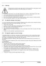
Page 44: ...e the ribbon cable Grease screw thread before replacing housing cover 8 6 Turning the signal converter housing To facilitate access to connecting indicating and operating elements on the compact flow...

Page 45: ...ic caustic flammable or water polluting liquids you are kindly requested To check and ensure if necessary by rinsing or neutralising that all cavities in the flow meter are free from dangerous substan...

Page 46: ...flow sensor data which are factory set The DSP data and data from the galvanic isolated inputs is used to calculate the various flow values In turn the galvanic isolated output circuits are updated I...

Page 47: ...reduced Combined with the use of the latest signal processing techniques DSP this results in a stable and reliable measurement 12 2 Three beam ultrasonic measurement The flow velocity measurement of t...

Page 48: ...Area H Block Pimpri Poona 411018 TEL 91 0 202 7442020 FAX 91 0 202 7442020 e mail pcu vsnl net Iran KROHNE Liaison Office North Sohrevardi Ave 26 Sarmad St Apt 9 Tehran 15539 TEL 98 21 874 5973 FAX 9...

Reviews: