9
Part B Signal Converter VFC 090
5. Operation of the signal converter
5.1
General
5.1.1 Starting up signal converter
When power is switched ON to signal convertor it displays
TEST
,
VFM 5090
&
Ver x.xx
and then goes to
measurement mode. In this initial sequence VFM 5090(I) carries out self diagnostics to check its own
functional elements and loads the configuration data from non-volatile memory. If any error(s) are detected in
power-ON diagnostics, the converter displays
FATAL.ERROR
since instrument has critical error(s) and is not
able to carry out normal measurements. If no start-up errors are detected the first measured parameter displayed
is the one being displayed when power supply was removed last time.
5.1.2 Measurement
Mode
In measurement mode, the parameters that the converter measures/computes are shown on the display in the
appropriate units. (See Sect. 5.2 for display details). As per the configuration, display can be either in non-
cyclic/cyclic mode. In non cyclic mode of display, use
é
key to see the next parameter on display. In cyclic
mode display shows all the parameters one after another, wherein each parameter is displayed for about 6
seconds.
5.1.3 Programming or menu mode
All the configurations/settings/test functions are grouped in the form of menu tree structure (see Sect. 5.3.1 for
details) and are accessible in the programming mode. Operator can view or alter the present settings and data
values by the use of functions available in this mode.
All changes made in the programming mode are stored temporarily until the operator quits to the
measurement mode and responds
YES
to an ‘
UPDATE
’ prompt. Only then the new changes are saved in
non-volatile memory and have appropriate effect on the operation of signal converter.
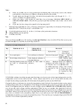
·
·
Even in the programming mode the converter “keeps working” as per present configuration. Simply stated,
the converter continues to measure (flow rate, totalizing of flow, P, T etc.) and control outputs (current and
frequency outputs) while in the programming mode.
5.1.4 Error
handling
Converter can detect errors during power-on diagnostics as well as when in normal measurement mode. Errors
are divided into two main categories viz. fatal errors and non-fatal errors. Fatal errors cause measurement to
stop since they are serious in nature. Non-fatal errors do not affect functionality of the converter.
If one or more errors are present, display (in the measurement mode) starts blinking. If programmed so, error
information is shown on display, interleaved between the display of two parameters.


