background image

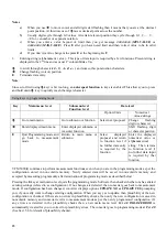
Fct. 1.3.6 0/4 mA POWER 

Enter the power value at which you want current 
output at its minimum 0 mA or 4 mA. 
 
LIMITS

 : 

No limits 

 
APPEARS

 : 

If meter type is


HEAT METER  or NET 

HEAT METER 

and

 Fct. 1.3.5. VARIABLE I 

is


POWER  

or 

 NET POWER. 

 
Fct. 1.3.7 20 mA POWER 

Enter the power value at which you want current 
output at its minimum 20 mA. 
 
LIMITS

 : 

No limits 

 
APPEARS

 : 

If meter type is


HEAT METER  

or

 NET 

HEAT METER 

and

 Fct. 1.3.5. VARIABLE I 

is


POWER  

or 

 NET POWER 

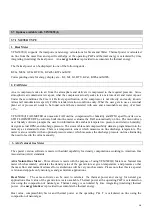
Fct. 1.4.0 FREQ. OUTP. F 

This submenu groups frequency output related 
functions. 

APPEARS – Always (Not when output type is RS 
485 or RS 232) 

Fct. 1.4.1 FUNCTION F


frequency output 

Choose 

YES 

to make frequency output active as per 

functions 

Fct. 1.4.2 

to 

Fct. 1.4.4 NO 

makes frequency 

output inactive (0 Hz) 

LIMITS - Not applicable. 

APPEARS - Always. (Not when output type is RS 
485 or RS 232)


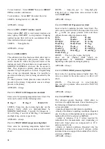
Fct. 1.4.2 RANGE F 

 frequency output range value 

The frequency output range value is the frequency 
that corresponds to max. flow (

Fct. 1.1.2

). The other 

point is always 0 Hz for 0 flow because frequency 
output is designed for use with external totalizers. It is 
also possible to define range f in terms of pulses/unit 
flow. 

Example - 

Assume max. flow (

Fct. 1.1.2

) = 1000 Kg/hr then  

range f = 10000 pulses/hr (at max. flow) and  
range f = 10 pulses/Kg are identical. The latter 
method is better because it is easy to infer that 
totalizer will have a least count of 0.1 Kg (10 pulses 
per Kg = 1pulse per 0.1 Kg) and totalizer 
programming will be independent of max. flow. The 
various options of units for 

RANGE F 

are given 

below. 


For volumetric flow - 

l

PULSE/hr 

l

PULSE/min 

l


PULSE/sec 

l

PULSE/m3 

l

PULS/Litre 

l


PULS/ft3 

l

PULS/cft 

l

PULS/cuft 

l


PULS/US.Gal 

l

PULS/UK. Gal 

For normalized volumetric flow - 

l

PULSE/hr 

l

PULSE/min 

l

PULSE/sec 

l

PUL

/NormM3


l

PULS/

NormL


l

PULS/Sft3 

l

PULS/Scft 

Or mass flow - 

l

PULSE/hr 

l

PULSE/min 

l


PULSE/sec 

l

PULS/Kg 

l

PULS/t 

l


PULS/Lb 

LIMITS - 0.0028 Hz TO 10,000 Hz. These limits are 
also applied when programming in pulses per unit 
flow units. All the necessary conversions for the same 
are done internally. 

APPEARS - If Fct. 1.4.1 FUNCTION F is YES. 

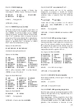
Fct. 1.4.3 PULS.WIDTH pulse width 

You can limit the duration of maximum active pulse 
width of the frequency output for frequencies less 
than or equal to 10 Hz. All options that may appear 
are listed below. Only the possible options that are 
available (depending on programming of  

Fct. 1.4.2 

RANGE F

) to choose are displayed during actual 

programming. 
 

l

500 mSec 

l

200 mSec 

l


100 mSec. 

l

50 mSec 

l

30 mSec 

l


50 % 

This function helps to minimize the overheating of 
electro-mechanical counter coils. 

LIMITS - Not applicable. 

APPEARS - if 

Fct. 1.4.1 FUNCTION F 

is 

YES. 

Fct. 1.4.4 VARIABLE F 

frequency output selection 

function 

Selects any one of the three options available for 
frequency output. 
Options are listed below : 

· 

FLOW 

· 

POWER 

· 

NET POWER 


LIMITS

 : 

Not applicable 

 
APPEARS – If meter type is 

HEAT METER 

or

 NET 

HEAT METER. 

For meter type

 HEAT METER

 , 

only flow and power options are available. For meter 
type 

NET HEAT METER

, all three options are 

available. 


28

Summary of Contents for VFM 5090

Page 1: ...4 2001 Vortex flowmeter Installation and operating Instructions VFM 5090 I ...

Page 2: ...3 3 Frequency pulse output F 6 3 3 4 Connection diagram for outputs j to m 7 8 4 Start up 8 Part B Signal converter VFC 090 5 Operation of the signal converter 9 5 1 General 9 5 1 1 Starting up signal converter 9 5 1 2 Measurement mode 9 5 1 3 Programming or menu mode 9 5 1 4 Error handling 9 5 2 Operating elements 10 5 3 Program organization and programming chart 11 5 3 1 Menu levels 11 5 3 2 Pro...

Page 3: ...1 Coding desired for entry into programming mode 46 6 2 12 Behaviour of outputs during programming 46 Part C Functional checks and Trouble shooting hints 7 Functional checks 47 7 1 Primary head functional checks 47 7 1 1 Vortex Sensor 47 7 1 2 Temperature Sensor 47 7 2 Signal converter functional checks 47 7 2 1 Self diagnostics 47 7 2 2 Display check 48 7 2 3 Current output check 48 7 2 4 Frequen...

Page 4: ...ion Items included with shipment Compact Vortex Flowmeter Installation and operating instructions Mounting bolts washers nuts Plastic cover wrench for electronic housing Optional upstream downstream pipes Programming chart indicating factory configuration settings Gaskets between primary head and pipeline Provided by customer All cables for electrical connections SIZE f Df SIZE f Df DN mm mm inch ...

Page 5: ...er supply and outputs and run them via an intermediate connection box see also Section 3 before installing the flowmeter 6 Orientation Turn the display board through 90 or 180 to obtain horizontal positioning of the display Turn the signal converter housing through 90 should that be more suitable for the location of the installation 7 State of Medium Ensure single phase flow Liquid droplets in gas...

Page 6: ...Sandwich Version Flanged Version 3 ...

Page 7: ...00 PN 16 40 64 DN 150 PN 16 40 DN 200 PN 10 16 and to ANSI 1 2 to 8 150 300 SORF Gaskets are supplied by us with flanged units Center the flowmeter by sight Check flange connections for leak tightness after flowmeter installation 2 4 Temperature and pressure measurements 2 4 1 Temperature measurement Installation in Vertical Pipe Run VFM 5090 I is always supplied with a temperature sensor This sen...

Page 8: ...rear terminal box 2 4 2 Pressure measurement with built in sensor Cable diameter To conform to protection category requirements observe the following recommendations Cable diameter 8 to 13 mm 0 31 to 0 51 Enlarge the inside diameter of the Screwed conduit entry by removing the appropriate onion ring s from the seal only if cables have extremely tight fit Fit blanking plug PG 16 and apply sealant t...

Page 9: ...put I The current output is galvanically isolated from all input and output circuits but not from frequency output F Therefore only one grounded receiver instrument may be connected to either current output I or frequency output F All functions and operating data are programmable see sections 5 6 1 6 2 8 Factory set data and functions are listed in the enclosed Configuration Sheet on settings This...

Page 10: ...tronic counters EC or switchgear input voltage 5 to 30V load current max 100 mA Ri 100 ohms selectable pulse widths see below Pulse width Fct 1 4 3 as a factor of frequency f pulse rate and maximum permissible load for active output term 4 1 4 2 or 4 4 1 4 2 see also Sect 6 2 9 Pulse width Frequency f F100 Load rating of active output Load current Load 500 ms 0 0028 Hz f 1 Hz 150 mA 160 Ohm 200 ms...

Page 11: ... 6 1 6 2 5 The flowmeter is ready for service 15 minutes waiting time after switching on the power source Increase flow velocity slowly and steadily Avoid abrupt changes in pressure in the pipeline If the process product is steam condensate may form initially and cause faulty measurements when the system is started up for the first time When powered the signal converter normally operates in the me...

Page 12: ...s 5 1 3 Programming or menu mode All the configurations settings test functions are grouped in the form of menu tree structure see Sect 5 3 1 for details and are accessible in the programming mode Operator can view or alter the present settings and data values by the use of functions available in this mode All changes made in the programming mode are stored temporarily until the operator quits to ...

Page 13: ...alizer value Measured Set temperature value Measured Set pressure value Velocity of medium Keys for programming the Signal Converter refer to Sect 5 4 for the functions of keys 6 o Magnetic Sensors to program the converter by means of a hand held bar magnet without having to open the housing refer to Sect 6 3 Function of sensors is same as keys Hold the bar magnet by the cap Apply other end of the...

Page 14: ...am for the signal converter consists of 5 levels The 1st line of display will identify the menu level during programming Function 4 0 is not accessible in usual manner and is explicitly generated due to errors detected by one or more plausibility checks refer Sect 5 6 11 ...

Page 15: ...0 E E E Fct 3 7 0 OPTIONS APPLICAT Fct 3 6 0 Fct 3 5 0 E E E FUNCTIONS E E E FUNCTIONS Actual 3 9 X FUNCTIONS Actual 3 8 X E E E Actual 3 7 X FUNCTIONS Actual 3 6 X FUNCTIONS Actual 3 5 X Fct 1 3 7 Fct 1 3 1 TO Fct 1 4 6 Fct 1 4 1 TO Fct 2 1 TO Fct 3 1 2 Fct 3 1 1 TO Fct 3 2 6 Fct 3 2 1 TO Fct 3 3 1 TO Fct 2 3 E Fct 3 3 0 USER DATA Fct 3 2 0 Fct 3 1 0 BASIS PARAM E E E CURR OUTP I Fct 1 3 0 FREQ O...

Page 16: ...ed Then continue as under y data level è E Return to submenu level or main menu level E Temporarily save proposal then with further data any or return function level Important 1 All changes made in programming mode are stored temporarily and do not affect operation of the signal converter until operator leaves menu mode and responds with UPDATE YES Exceptions all 2 X test functions 2 Main menu lev...

Page 17: ...ge Fct 1 2 6 as YES for error messages If in non cyclic mode Fct 1 2 7 as NO In cyclic mode the key has no function E followed by é è Resets LINE INTR error Function of keys in programming mode Programming and other functions are grouped in a menu tree structure To navigate in the menu tree use keys as follows è To go into the branch i e from main menu level to submenu level or submenu level to fu...

Page 18: ...character position E Quit Programming mode and go back to measurement mode Return to main menu or submenu Select displayed proposal and return to function level if no further data entry is required by the function Enter the displayed numerical value or alphanumerical string Then returns to function level if no further data input is required by that function VFM 5090 I continues to perform measurem...

Page 19: ... q max Corrective action depends on application process If flow rate exceeds too much further it may damage entire instrument physically LOW TEMP OPR N Operating temp lower than limit Corrective action depends on the process HIGH TEMP OPR N Operating temp higher than limit Corrective action depends on the process LOW PRES OPR N Operating pressure lower than limit Take corrective action depending o...

Page 20: ...her quantities Math functions of the instrument software will generate errors for cases such as divide by zero square root of a ve number etc Such errors are never expected to occur in VFM 5090 I If due to corruption of memory data or in the unlikely event of a software bug any math error occurs instrument cannot function since there is no simple recovery and it annunciates errors such as HALTED R...

Page 21: ...ly software prompts the user for information like ambient temperature pressure and relative humidity design actual RPM and discharge pressure The steam tables and compressibility data are programmed into the memory as a standard feature There is a temperature sensor which measures on line discharge temperature The meter is also available with an optional pressure sensor which measures the discharg...

Page 22: ...line from mass flow and specific enthalpy both at the inlet of the process and at the outlet The difference between these two values is the net thermal power The net thermal energy is calculated by time integrating totalizing the net thermal power The mass flow is measured by the VFM along with the temperature at that point The temperature at the exit of the process is also measured and transmitte...

Page 23: ...ty 1 Stop bit at a baud rate of 1200 bits sec Connection diagram for RS 232 output is given below Please note that the RS 232 output uses the same terminals as used by the Frequency output Consequently when the RS 232 option is present frequency output function can not be used 5 6 4 RXD 4 1 TXD 4 2 GND 1 2 CHARACTER FORMAT Measured values or Error messages which appear on instrument display in nor...

Page 24: ...isolated from all inputs and output circuits but not from current output Therefore only one grounded receiver may be connected to either RS 485 output or current output Operating data for RS 485 output is not programmable as in case of current or frequency output VFM 5090 I always uses the following operating data 1 Start bit 8 Data bits Odd Parity 1 Stop bit at a baud rate of 1200 bits sec Connec...

Page 25: ...e value QNval Numeric value of measured normalised flowrate QNunit Unit of the normalised flowrate value QMval Numeric value of measured mass flowrate QMunit Unit of the mass flowrate value TVval Numeric value of computed totalised volumetric flow TVunit Unit of the totalised volumetric flow value TNval Numeric value of computed totalised normalised flow TNunit Unit of the totalised normalised flo...

Page 26: ...f Measured Value unit and error mesg fields The user system may use the 2 space characters and CR LF characters as delimiters for fields 2 4 RS 485 OUTPUT FOR AGA NATURAL GAS METER RS485 option given for AGA supported software is same except for some transmitted values These values are as follows CF CFval sp sp CFunits sp sp TH THval sp sp THunits sp sp HE nn Err sp sp m mesg m cr lf If there are ...

Page 27: ... sp LOW FLOW cr lf Note that the actual number of characters in each format is not fixed and depends on the contents of Measured Value unit and error mesg fields The user system may use the 2 space characters and CR LF characters as delimiters for fields Note In this software QFval computed FAD value is not applicable 24 ...

Page 28: ...d be within the measuring range for the given primary data 3 1 x functions and application data 3 5 x functions The frequency output range value directly corresponds to max flow If flow rate exceeds max flow an error condition HIGH FLOW is generated which may affect current output depending on programming of Fct 1 3 2 RANGE I The following units are available to choose from depending on programing...

Page 29: ...Scft hr l Scft min l Scft sec l MAX FLOW For mass flow l Kg hr l kg min l kg sec l T hr l T min l T sec l Lb hr l Lb min l Lb sec l MAX FLOW Note that the list is same as for Fct 1 1 2 except for an additional unit MAX FLOW to display flow rate as a percentage of max flow LIMITS Not applicable APPEARS Always Fct 1 2 2 TOTAL UNITS totalizer unit for display Totalized flow may be displayed in one of...

Page 30: ...t error indication on current output When a range with suffix of 22 E or 2 E is selected then it means that current output will give 22mA or 2mA error output if any error s are present in the instrument Range options are listed below l 0 20 l 4 20 l 0 20 22 E l 4 20 22 E l 4 20 2 E LIMITS Not applicable APPEARS If Fct 1 3 1 FUNCTION I is YES Fct 1 3 3 0 4mA FLOW Enter the flow value at which you w...

Page 31: ...1 Kg and totalizer programming will be independent of max flow The various options of units for RANGE F are given below For volumetric flow l PULSE hr l PULSE min l PULSE sec l PULSE m3 l PULS Litre l PULS ft3 l PULS cft l PULS cuft l PULS US Gal l PULS UK Gal For normalized volumetric flow l PULSE hr l PULSE min l PULSE sec l PUL NormM3 l PULS NormL l PULS Sft3 l PULS Scft Or mass flow l PULSE hr...

Page 32: ...hange to test values so you should take appropriate actions depending on how you are using current output Place current meter in series with current loop then select one of the following values l 0 mA l 2 mA l 4 mA l 10 mA l 20 mA l 22 mA Selecting any value will cause that current to flow so that you can check on meter Select CONT YES to test other current value or CONT NO to end When the menu fu...

Page 33: ... that the selection will have effect when one leaves menu and respond with YES to save changes LIMITS Not applicable APPEARS Always Fct 3 2 2 ENTRY CODE 1 entry code 1 password Select YES if password should be checked to access the menu Use password to prevent configuration changes by an unauthorized person Answering NO means password is not required to enter menu LIMITS Not applicable APPEARS Alw...

Page 34: ...er limit The value is entered in the same units as in Fct 3 3 1 above LIMITS temp_low_opr to temp_high_phy temp_low_opr is temperature value entered in Fct 3 3 1 TEMP LOW APPEARS Always Fct 3 3 3 PRES LOW pressure low limit Enter value for operating pressure lower limit The value can be entered in the following units Unit with the _g suffix are gauge pressure units and those without the same absol...

Page 35: ... 5 3 SAT P T use saturation P or T For saturated steam only one of the operating temperature or pressure is needed for density calculation Select whether you are going to specify saturation temp or pressure from the following options l SAT TEMP l SAT PRES Actual value of temp or pressure is to be entered under Fct 3 5 6 TEMP OPR or Fct 3 5 7 PRES OPR LIMITS Not Applicable APPEARS if fluid is STEAM...

Page 36: ...pressure range given in Fct 3 3 3 PRES LOW and Fct 3 3 4 PRES HIGH APPEARS Does not appear if 1 Medium is saturated steam Fct 3 5 3 SAT P T is set to SAT TEMP or 2 Fluid is Liquid Fct 3 5 8 DENS OPR density at operating P T Enter the density of medium at operating pressure and temp conditions The value can be entered in one of the following units l Kg m3 l Kg Litre l Lb ft3 l Lb cft LIMITS 0 6 to ...

Page 37: ...one of the units same as in Fct 3 3 3 and the corresponding milli volt value LIMITS 0 to 40 Bar for P11 0 to 25 mV for V11 APPEARS if Fct 3 6 2 P SENSOR is YES and fluid is not LIQUID Fct 3 7 3 P12 V12 calibration point 2 at T1 Enter pressure value same unit assumed as in Fct 3 7 2 and the corresponding milli volt value LIMITS 5 to 100 Bar for P12 40 to 125 mV for V12 APPEARS If Fct 3 6 2 P SENSOR...

Page 38: ...AT STEAM Fct 3 8 6 NT PWR UNITS Net thermal power units Thermal power can be displayed in any one of the following units KJ hr BTU hr GJ hr MW MJ h KCAL hr KW NO DISPLAY LIMITS Not applicable APPEARS If meter is NET HEAT METER Fct 3 8 7 NT PWR UNITS Net thermal energy units Thermal energy can be displayed in any one of the following units KJ MJ GJ BTU KcaL KWH MWH NO DISPLAY LIMITS Not applicable ...

Page 39: ...alculation due to offset in same temperature reading if measured by two different temperature sensors LIMITS max 3 deg C APPEARS If meter type is NET HEAT METER Fct 3 9 0 FAD PARA This submenu level has functions which allow user to program all operating data for FAD application APPEARS If meter type is FAD meter Fct 3 9 1 FAD UNITS units for FAD Select unit for display of parameter FAD Volume flo...

Page 40: ...hich need be corrected When you correct the parameter that function instantly disappears from the 4 x list and when all such function parameters are corrected menu automatically returns to 4 0 level APPEARS if plausibility test detects errors when attempting to save the configuration in non volatile memory Fct 4 1 K FACTOR k factor of the primary Enter the primary constant k factor value This valu...

Page 41: ...flow rate desired Max flow should be within measuring range for the given primary data 3 1 x functions and application data 3 5 x functions The frequency output range value directly corresponds to max flow If flow rate exceeds max flow an error condition HIGH FLOW is generated which may affect current output depending on programming of Fct 1 3 2 RANGE I The following units are available to choose ...

Page 42: ... max flow Fct 1 1 2 The other point is always 0 Hz for 0 flow because frequency output is designed for use with external totalizers It is also possible to define range f in terms of pulses unit flow Example Assume max flow Fct 1 1 2 1000 Kg hr then range f 10000 pulses hr at max flow and range f 10 pulses Kg are identical The latter method is better because it is easy to infer that totalizer will ...

Page 43: ...3 hr l FAD ft3 min l FAD ft3 sec l FAD cft hr l FAD cft min l FAD cft sec For normalized volumetric flow l Norm m3 hr l Norm m3 min l Norm m3 sec l Norm Litre hr l Norm Litre min l Norm Litre sec l Sft3 hr l Sft3 min l Sft3 sec l Scft hr l Scft min l Scft sec l MAX FLOW only for Fct 1 2 1 FLOW UNITS For mass flow l Kg hr l Kg min l Kg sec l T hr l T min l T sec l Lb hr l Lb min l Lb sec l MAX FLOW...

Page 44: ...t sec FREQUENCY OUTPUT UNITS Refer to function Fct 1 4 2 RANGE F frequency output range value Fct 4 9 RANGE F frequency output range value Units for RANGE F For volumetric flow l PULSE hr l PULSE min l PULSE sec l PULSE m3 l PULS Litre l PULS ft3 l PULS cft l PULS cuft l PULS US Gal l PULS UK Gal For normalized volumetric flow l PULSE hr l PULSE min l PULSE sec l PUL Norm m3 l PULS Norm L l PULS S...

Page 45: ...he top left of the display which is used to acknowledge the keys Programming Measurement mode settings are as follow To allow selection of units for all measured parameters Refer to Sect 6 1 Fct 1 2 1 to 1 2 6 Select what parameters to include in display cycle Refer to Sect 6 1 Fct 1 2 2 to 1 2 6 Select display mode cyclic non cyclic and error messages to not to appear in display cycle Refer to Se...

Page 46: ...ting temperature and pressure conditions Refer Fct 3 5 6 TEMP OPR and Fct 3 5 7 PRES OPR density of medium at operating conditions Required only if software within instrument does not support the medium Fct 3 5 2 is selected as NONE Refer Fct 3 5 8 DENS OPR normal or reference P T values required for normalized flow measurements only depending on Fct 1 1 1 Usual values are temp norm 0 or 20 Deg C ...

Page 47: ...ct to the flow rate Refer to figure I 1 and Sect 6 Fct 1 3 5 VARIABLE I Current output selection function You can have current output proporational to any of flow power and net power This facility is available if the meter is Heat meter or Net Heat meter only Since validity of the minimum and maximum values of net heat meter is not checked please ensure that the value for 20 mA is greater than tha...

Page 48: ... set via Fct 1 4 2 at 2000 litres per second 2000 pulses per second 1 pulse per litre as before Example of pulses time Full scale setting qmax 1000 Litre sec set via Fct 1 1 2 RANGE F 1000 PULSE sec set via Fct 1 4 2 Pulse value is then 1 pulse per litre Changeover of Full scale setting qmax 2000 Litre sec ser via Fct 1 1 2 RANGE F unchanged 1000 PULSE sec set via Fct 1 4 2 Pulse value is now 1 pu...

Page 49: ...F1 Fct 3 2 1 LANGUAGE offers choice of the display text language The following options are available l ENGLISH l GERMAN l FRENCH Fct 3 2 2 ENTRY CODE 1 set to YES for coding The entry code is to be given under Fct 3 2 3 CODE 1 The entry code consists to 9 key strokes of the 3 keys in any combination Programming of the VFM 5090 I is on line meaning that the instrument keeps working even when it is ...

Page 50: ...reverse order 7 1 2 Temperature Sensor PT 1000 temperature sensor can be checked by measuring its resistance Always switch OFF power source before commencing work Follow the steps 1 2 same as in the above Section 7 1 1 3 Remove the temperature sensor cable at location Y of the preamplifier board Pull cable by its end connector and not by cable itself 4 Resistance between the 2 pins should be withi...

Page 51: ...d to side 5 Remove plugs X Y Z to remove wires from d pressure sensor temperature sensor and vortex sensor respectively 6 Remove screws D using a screwdriver for Philips head screws size 2 blade length 200 mm 8 and carefully remove the complete electronics 7 Remove the fuse from its black plastic housing located on power supply board for checking Replace the fuse if necessary Rating of fuse is dep...

Page 52: ... may be appearing intermittantly Check programming of Fct 3 1 2 K Factor which should be same as on the name plate Meter not properly centered on the pipeline The axis of meter bore should be aligned with that of pipe Gasket at the meter are protruding into pipe bore Gaskets must not project into effective cross section of the pipe Irregularities on the surface of the pipe bore The pipe bore shoul...

Page 53: ...re 9 2 Electrical connection The power cable and signal cable should be routed to the terminal compartment through separate cable glands for field connections The cables should have at least 9mm 0 35 outer diameter ensuring firm holding of cables and sealing in the cable glands Refer Diagram given for field connections FIELD CONNECTION DIAGRAM 10 Process Pressure and Temperature Nominal pressure i...

Page 54: ...ll the unit out holding the montage holder 6 Replace the unit in reverse order from 5 to1 Caution Ensure that the earthing platelet on barrier board is firmly connected to the enclosure by screw SE Ensure that the Window cover is screwed down firmly so that it cannot be opened by hand Ensure that the sensor cables are properly latched to y z x 2 3 5 pin connectors on barrier board Ensure that the ...

Page 55: ......

Page 56: ...13 Nameplates of VFM 5090 I Ex 51 52 ...

Page 57: ... 108 07 75 246 06 2432 39 1431 65 2223 58 1308 75 150 6 159 3 6 27 154 2 6 07 5 91 19 37 423 69 261 54 397 00 245 06 75 246 06 5381 28 3167 30 5042 23 2967 74 200 8 206 5 8 13 202 7 7 98 5 91 19 37 711 97 439 49 686 01 423 46 75 246 06 9042 61 5322 28 8712 87 5128 20 Range Limits for liquids based on water at 20o C 68o F Meter size Inside diameter f di Vmin Qmin Vmax Qmax DIN ANSI DIN ANSI DIN ANS...

Page 58: ...1627 66 1740 88 29177 52 2076 18 33138 87 2682 87 39372 70 3260 09 44728 76 3831 85 49505 32 4212 22 52658 51 Flowrate Qm in Kg hr for different pressure P and density r DN Inside P 1Kg cm2_ g P 3 5 Kg cm2_ g P 5 2 Kg cm2_ g P 7 Kg cm2_ g P 10 5 Kg cm2_ g P 14 Kg cm2_ g P 17 5 Kg cm2_ g P 20 Kg cm2_ g ANSI Dia di r 1 12482 Kg m3 r 2 39175 Kg m3 r 3 22667 Kg m3 r 4 10067 Kg m3 r 5 78855 Kg m3 r 7 4...

Page 59: ...2 47646 73 3853 83 64782 76 4571 63 72906 86 5908 67 86630 47 7181 48 98420 95 8442 06 108935 90 9560 30 118547 51 Flowrate Qm in lbs hr for different P and density r DN Inside P 15 PSIG P 50 PSIG P 75 PSIG P 100 PSIG P 150 PSIG P 200 PSIG P 250 PSIG P 300 PSIG ANSI Dia di r 0 072lbs ft3 r 0 1498 lbs ft3 r 0 2036 lbs ft3 r 0 2569 lbs ft3 r 0 3627 lbs ft3 r 0 4682 lbs ft3 r 0 5736 lbs ft3 r 0 6793 ...

Page 60: ...ion h in mPA s or in centipoise Maximum volumetric flowrate Qmax in m3 hr Minimum volumetric flowrate Qmin in m3 hr Refer to page 64 65 66 for dimension of meter inside diameter The following limits apply to operation Reynolds number at min flow Re 20 000 for linear measurements Minimum detectable flow velocity Vmin See page 59 Diagram III Maximum flow velocity Vmax 135 7306 Örop for sizes DN25 to...

Page 61: ...ured value for DN25 to 200 ANSI1 to 8 2 5 of measured value for DN10S to 20 ANSI 3 8 S to Repeatability 0 5 of measured value Product Temperature error Compensated by software only Materials SR NO DESCRIPTION MATERIAL REMARKS 1 Housing Stainless Steel A351 CF3M 316L Stainless Steel A351 CF8 304 Upto size DN100 4 From DN150 6 to DN200 8 2 Vortex shedding body Unalloyed Titanium No 3 7035 as standar...

Page 62: ...3 2 7 5 3 2 10 1 A B C D E F G H I J K 2 3 5 7 10 2 3 5 7 100 2 3 5 71000 2 0 1 3 5 7 10000 1 1 02 0 73 0 44 29 15 10 0 073 0 044 0 029 0 015 0 010 0 0 073 0 0044 0 0029 0 0015 1 45 100 62 1 10 100 1000 10000 2 3 5 7 2 3 5 7 2 3 5 7 2 3 5 7 m h US GPM 3 7 5 3 2 7 5 3 2 7 5 3 2 100 10 A B C D E F G H I J K 2 3 5 7 1 2 3 5 7 10 2 3 5 7100 2 3 5 7 1000 0 10 15 7 25 4 35 2 90 1 45 1 02 0 73 0 44 0 29 ...

Page 63: ...eam 0 1 1 10 0 1 1 10 100 Density kg m3 Velocity Vmin m s 0 1 1 10 100 0 1 1 10 100 Density kg m3 Velocity vm in m s A B C D Curve Meter Size DIN ANSI A B C D DN 10 S 3 8 S DN 10 3 8 DN 15 1 2 DN 20 3 4 DN10S 3 8 S TO DN20 3 4 DN25 1 TO DN200 8 Diagram IV Tm 0 C 0 F Tu 0 C 0 F ...

Page 64: ...Housing signal converter with separate connection compartment Material die cast aluminium Protection category EN 60529 IEC 529 IP 65 IP 67 better than NEMA 4 4X Current output Operating data programmable galvanically isolated not from frequency output Current 0 4 to 20 mA corresponding to flow values independently programmable with min span equal to 20 of full scale Accuracy 0 1 of FS Temp coeffic...

Page 65: ...1 1 160 µs 50 µs 0 0028 Hz 0 0028 Hz 0 0028 Hz 3 Hz 0 0028 Hz 5 Hz 0 0028 Hz 6 Hz 10 Hz 10000 Hz 2547 Hz f f f f f f f f f f 1 Hz 2 Hz 3 Hz 5 Hz 5 Hz 10 Hz 6 Hz 10 Hz 1000 Hz 2547 Hz 10000 Hz 150 150 150 60 150 60 150 80 25 25 25 mA mA mA mA mA mA mA mA mA mA mA 160 160 160 400 160 400 160 300 1000 1000 1000 Ohm Ohm Ohm Ohm Ohm Ohm Ohm Ohm Ohm Ohm Ohm 61 ...

Page 66: ...DIMENSION DETAILS 62 ...

Page 67: ...DN150 3 6 di c 204 8 03 156 6 14 a ø122 4 8 b PG 16 ø122 4 8 a di c 186mm 7 32 240mm 9 45 For EX Version Flanged ver DN200 8 204 8 03 ø122 4 8 156 6 14 PG 16 b Small Size DN10s TO DN20 3 8 s TO 3 4 204 8 03 156 6 14 l a ø122 4 8 b PG 16 For EX Version 240mm 9 45 186mm 7 32 c 63 ...

Page 68: ...136 5 35 393 15 49 227 8 94 7 5 16 4 8 3 18 2 3 150LBS 78 3 07 65 2 56 1025 00 40 35 387 15 23 136 5 35 401 15 77 220 8 66 7 5 16 4 8 3 18 2 3 300LBS 78 3 07 65 2 56 1025 00 40 35 387 15 23 136 5 35 401 15 77 220 8 66 7 5 16 4 8 3 18 2 DN100 PN16 107 1 4 22 80 3 15 1280 00 50 39 406 15 98 159 6 26 408 16 07 251 9 88 8 5 18 7 9 3 20 5 DN100 PN40 107 1 4 22 80 3 15 1280 00 50 39 406 15 98 159 6 26 4...

Page 69: ...12 16 21 412 16 21 259 10 20 12 5 27 6 13 3 29 4 DN80 PN64 82 5 3 25 250 9 84 427 16 80 427 16 80 267 10 50 14 0 30 9 14 8 32 7 DN80 PN100 82 5 3 25 250 9 84 419 16 50 419 16 50 274 10 79 15 7 34 6 16 5 36 4 3 150LBS 78 3 07 250 9 84 414 16 30 414 16 30 247 9 73 13 3 29 3 14 1 31 0 3 300LBS 78 3 07 250 9 84 423 16 66 423 16 66 256 10 09 14 8 32 6 15 6 34 3 DN100 PN16 107 1 4 22 250 9 84 444 17 48 ...

Page 70: ...4 37 13 3 8 1 2 NB ANSI150 12 6 0 5 826 32 5 356 14 02 154 6 05 232 9 14 665 26 2 11 70 25 80 12 50 27 56 1 2 NB ANSI300 12 6 0 5 826 32 5 356 14 02 154 6 05 232 9 14 665 26 2 12 16 26 81 12 96 28 58 3 4 NB ANSI150 12 6 0 5 826 32 5 356 14 02 154 6 05 232 9 14 665 26 2 12 09 26 66 12 89 28 42 3 4 NB ANSI300 12 6 0 5 826 32 5 356 14 02 154 6 05 232 9 14 665 26 2 13 16 29 02 13 96 30 78 1 NB ANSI150...

Page 71: ...edding generates a so called Karman Vortex Street with alternating pressure conditions whose frequency f is proportional to the flow velocity v The non dimentional Strouhal number S primary head constant describes the relationship between vortex shedding frequency F in Hz width b of the body and mean flow velocity v in m s F b v S The flexural vibration of the vortex shedding body is picked up in ...

Page 72: ...Pipe for U S D S Assembly Note 1 Material C S seamless Pipe ASTM A106 GR B 2 Unless specified dimentions are in mm 68 ...

Page 73: ...ze Flange Pressure Class Material Designation Heat Code Material C S SA 516 Gr 60 Unless specified dimentions are in mm Note Flanges as per the B16 5 Surface finish 32 to 63 um Details to be stamped Manufacturers Name or trademark Flange Size Flange Pressure Class Material Designation Heat Code Material C S SA 516 Gr 60 Unless specified dimentions are in mm 69 ...

Page 74: ...s per ANSI B16 5 Surface finish 32 to 63 um Details to be stamped Manufacturers Name or trademark Flange Size Flange Pressure Class Material Designation Heat Code How to Stamp Flange Recess Facing away operator Material C S SA 516 GR 60 Unless specified dimentions are in mm 70 ...

Page 75: ...DIN 2501 Surface finish 32 to 63 um Details to be stamped Manufacturers Name or trademark Flange Size Flange Pressure Class Material Designation Heat Code How to Stamp Flanges Facing operator Material C S SA 516 GR 60 Unless specified dimentions are in mm 71 ...

Page 76: ...s per DIN 2501 Surface finish 32 to 63 um Details to be stamped Manufacturers Name or trademark Flange Size Flange Pressure Class Material Designation Heat Code How to Stamp Flanges Recess Facing away operator Material C S SA 516 GR 60 Unless specified dimentions are in mm 72 ...

Page 77: ...ly for SW Note One set of U S Assly and one set of D S Assly is to be supplied To be painted with heat resistant paint Flanges to welded off center Welding std Ad Merkblatt B8 Material C S Unless specified dimentions are in mm 73 ...

Page 78: ... as per JIS B2210 Surface finish 32 to 63 um Details to be stamped Manufacturers Name or trademark Flange Size Flange Pressure Class Material Designation Heat Code How to Stamp Flange RF Facing operator Material C S SA 516 GR 60 Unless specified dimentions are in mm 74 ...

Page 79: ...e One set of U S Assly and one set of D S Assly is to be supplied To be painted with heat resistant paint Flanges to welded off center Welding std Ad Merkblatt B8 Material C S Unless specified dimentions are in mm SW Vortex Flowmeter with U S D S 75 ...

Page 80: ...ES WITH 7D 5D LOCATING PIPES 1 AND 1 5 METER MATING FLANGES WILL 300LBS ONLY BUT PIPE MATING FLANGES CAN BE 150LBS 300LBS Face to face distance for DN 100 4 units is 80 mm so one to one replacement with the old design in this case is not possible 76 ...

Page 81: ...Krohne Marshall Ltd A 34 35 MIDC H Blk Pimpri Pune 411 018 Tel 91 0 20 7470171 Fax 91 0 20 7477049 After Office Hrs 020 7477762 Subject to change without notice ...

Reviews: