BCU 560, BCU 565 · Edition 02.16
100
Parameters
11 .11 Functions of terminals 50, 51, 65, 66, 67 and
68
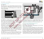
The BCU is informed via terminal 50 by a separate automation
system that purging is currently being performed.
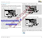
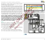
Terminals 51, 65, 66, 67 and 68 can each be assigned a logi-
cal AND gating with one of the inputs for the safety functions
(terminals 46 – 50) using an appropriate parameter. If AND
gating is required, the input concerned can be enabled.
Terminal 51 can also be used as a feedback input for the
maximum capacity position when operated with IC 40/RBW.
11 .11 .1 Function of terminal 50
Parameter 68
The BCU..F1, F2 or F3 supports centrally-controlled pre-purge
or post-purge. In the case of multiple burner applications,
burners with mechanical combustion air supply are used.
The air for combustion and pre-ventilation is supplied by a
central fan controlled by a separate automation system. The
automation system sends a signal to terminal 50 during purg-
ing. At this point, the BCU opens the air actuator (actuator, air
valve) regardless of the status of the other inputs. The display
shows
P 0
.
Parameter 68 = 23: purge with Low signal
Parameter 68 = 24: purge with High signal
11 .11 .2 Function of terminal 51
Parameter 69
Parameter 69 = 0: Off
Parameter 69 = 8: AND with input at terminal 46 (emergency
stop)
Parameter 69 = 9: AND with input at terminal 47 (air
min.
pres-
sure switch)
Parameter 69 = 10: AND with input at terminal 48 (air flow
pressure switch)
Parameter 69 = 13: IC 40/RBW feedback of position for maxi-
mum capacity, see page 83 (Parameter 40 = 3: with RBW.).
11 .11 .3 Function of terminal 65
Parameter 70
Parameter 70 = 0: Off
Parameter 70 = 8: AND with input at terminal 46 (emergency
stop)
Parameter 70 = 9: AND with input at terminal 47 (air
min.
pres-
sure switch)
Parameter 70 = 10: AND with input at terminal 48 (air flow
pressure switch)

