VAA · Edition 09.21
EN-3
➔
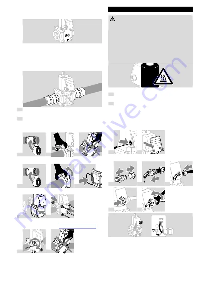
The inlet pressure p
u
and the outlet pres-
sure p
d
can be measured using the pressure
test points on both sides, see accessories.
p
d
p
u
➔
The seals in some gas compression fittings
are approved for temperatures of up to 70°C
(158°F). This temperature limit will not be ex-
ceeded if the flow through the pipe is at least
1 m
3
/h (35.31 SCFH) of gas and the maxi-
mum ambient temperature is 50°C (122°F).
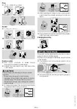
1
Remove the adhesive label or screw cap from the
inlet and outlet.
2
Obey the direction of flow as marked on the hous-
ing.
VAA with flanges
a
b
c
VAA without flanges
a
b
c
➔
O-ring (Fig.
c
) must be fitted.
d
e
➔
Note the recommended tightening torques for the
connection parts! See page 7 (Technical data)
f
g
WIRInG
WARnInG
Risk of injury!
Please observe the following to ensure that no
damage occurs:
– Electric shocks can be fatal! Before working on
possible live components, ensure the unit is
disconnected from the power supply.
– The solenoid actuator heats up during
operation. Surface temperature approx. 85°C
(approx. 185°F).
➔
Use temperature-resistant cable (> 80°C).
1
Disconnect the system from the electrical power
supply.
2
Shut off the air supply.
➔
Wiring to EN 60204-1.
➔
Push through and remove the knock-out in the
connection box before removing the cover. If the
M20 cable gland or plug is already fitted, it is not
necessary to remove the knock-out.
3
4
M20 cable gland
a
b
c
d
e
(+)
LV1
N
(-)

