VAA · Edition 09.21
EN-4
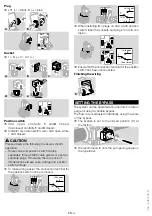
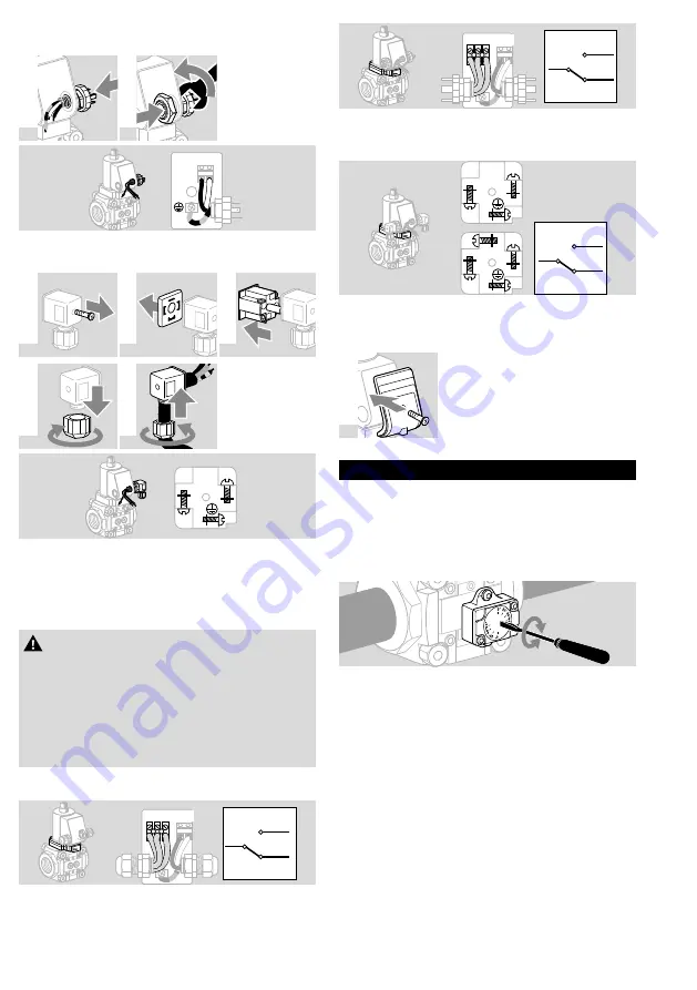
Plug
➔
LV1 (+) = black, N (–) = blue
a
b
(+)
LV1
N
(-)
socket
➔
1 = N (–), 2 = LV1 (+)
a
b
c
d
e
2
1
Position switch
➔
VAA open: contacts
1
and
2
closed,
VAA closed: contacts
1
and
3
closed.
➔
Indicator of position switch: red = VAA open, white
= VAA closed.
CAUtIon
Please observe the following to ensure smooth
operation:
– Route valve and position switch cables
separately through M20 cable glands or use two
separate plugs. Otherwise, there is a risk of
interference between valve voltage and position
switch voltage.
➔
To make wiring easier, the connection terminal for
the position switch can be removed.
1 3
2
LV1
(+)
N
(-)
1
COM
2
Valve open
Valve closed
3
1 3
2
LV1
(+)
N
(-)
1
COM
2
Valve open
Valve closed
3
➔
When installing two plugs on VAA a with position
switch: label the sockets and plugs to avoid con-
fusion.
2
1
3
2
1
1
COM
2
Valve open
Valve closed
3
➔
Ensure that the connection terminal for the position
switch has been reconnected.
Finishing the wiring
5
settInG tHe BYPAss
The system can be operated at burner low-fire rate or
purge air using a variable bypass.
The flow rate is adjusted individually using the scale
on the bypass.
➔
The bypass is set to the closed position (0°) at
the factory.
➔
We recommend to note the set opening angle on
the type label.

