DG..H, DG..N, DG..I · Edition 03.22
EN-5
3
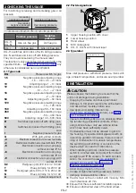
Connect an ohmmeter.
COM
3
NC
1
NO
2
NO
2
NC
1
COM
3
4
Set the switching point using the hand wheel.
5
Connect a pressure gauge.
6
0
1 cm = 1 mbar
(0.4" = 0.4"WC)
7
Apply pressure. In doing so, monitor the switching
point on the ohmmeter and the pressure gauge.
8
If the DG..H, DG..N, DG..I does not trip at the de-
sired switching point, correct the adjusting range
using the hand wheel. Relieve the pressure and
repeat the process.
5.1 Adjusting range
type
Adjusting
range
1)
[mbar]
Reset
pressure
2)
[mbar]
Max. inlet
pressure
p
max.
DG 10H,
DG 10N
1–10
0.4–1
600
DG 50H,
DG 50N
2.5–50
1–2
600
DG 150H,
DG 150N
30–150
5–15
600
DG 500H,
DG 500N
100–500
15–25
600
type
Adjusting
range
1)
[mbar]
switching
differen-
tial
3)
[mbar]
Max. inlet
pressure
p
max.
DG 1,5I
-1.5 to -0.5
and
+0.5 to +3
0.2–0.5
± 100
DG 12I
-12 to -1 and
+1 to +7
0.5–1
± 100
DG 18I
-2 to -18
0.5–1.5
± 100
DG 120I
-10 to -120
4–11
± 600
DG 450I
-80 to -450
10–30
± 600
1) Adjusting tolerance = ± 15% of the scale value.
2) Difference between switching pressure and possible reset.
3) Mean switching differential at min. and max. setting.
type
Deviation from the switching
point during testing pursuant
to en 1854 Air pressure
switches
DG..H, ..N, ..I
± 15%
DG 1,5I
± 15% or ± 0.4 mbar
DG 12I
± 15% or ± 0.5 mbar
DG 18I
± 15% or ± 0.5 mbar
6 tIGHtness test
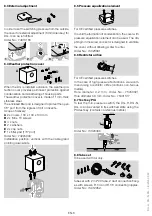
Check all gas ports used for tightness.
1
Shut off the downstream gas pipeline close to the
valve.
2
Open the valve and the gas supply.
➔
N
2
= 900 mbar, max. 2 bar (13 psi, max. 29 psi)
< 15 min.
3
N
2
4
7 MAIntenAnCe
In order to ensure smooth operation, check the tight-
ness and function of the pressure switch every year,
or every six months if operated with biogas.
➔
A function check can be carried out in case of falling
pressure monitoring e.g. with the PIA.
➔
After carrying out the maintenance work, check
for tightness, see page 5 (6 Tightness test).
8 ACCessoRIes
8.1 Connecting set
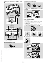
For monitoring a minimum and maximum inlet pressure
with two pressure switches attached to one another.
Order No.: 74912250
1
2
1
2
2
2 x
3
1
1 x
4
8.2 Filter pad set
To protect the electrical contacts in the DG..H, DG..N,
DG..I from dirt particles in the surrounding air or in the
medium, use a filter pad at the 1/8" negative pressure
port. As standard on IP 65 units.
5-piece filter pad set, Order No.: 74916199


