background image

GFK · Edition 05.19

EN-2

CHeCKInG tHe UsAGe

Gas filter GFK is used for filtration of the fuel gas and 
combustion air supply to all gas consuming appliances. 

This function is only guaranteed when used within the 

specified limits – see  page 3 (Technical data). Any 
other use is considered as non-compliant. 

type code

GFK


 Gas filter 

15 – 250


 Nominal size 

t


  T-product  

R


 Rp internal thread 

F


 Flanged connection to ISO 7005 

n


 NPT internal thread 

A


 ANSI flange 


 Max. inlet pressure p

u max.


10


 1 bar 

40


 4 bar (58 psig) 

60


 6 bar 

-3


 Screw plug at the inlet and outlet 

-6


 Pressure test point at the inlet and outlet 


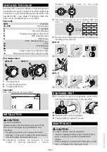
Part designations

GFK..F

GFK..R

1

1

3

2

2

Housing cover

Lower housing section

Pressure test point

type label

Max. inlet pressure: see type label.

D-49018 Osnabrück, Germany

GFK 

p

u max


InstALLAtIon

 CAUtIon

Incorrect installation
Please observe the following to ensure that the 
GFK is not damaged during installation and 
operation:


– Dropping the device can cause permanent 

damage. In this event, replace the entire device 
and associated modules before use.


Installation position: as required, in hori-

zontal or vertical pipework  – recom-

mended: housing cover to the side.


The housing must not be in contact with ma-

sonry, minimum clearance 20  mm (0.79").


> 20 mm


We recommend applying a protective coating when 
installing in the open air.

GFK..R

 1 


 2 


 3 


 4 
GFK..F

 1 


 2 


 3 

tIGHtness test

 1 

To be able to check the tightness, shut off the 
downstream pipeline close to the gas filter.

 2 


 3 

 4 

Tightness OK: open the pipeline.


Pipeline leaking: replace the seal.

MAIntenAnCe

 CAUtIon

In order to ensure smooth operation:


– clean or replace the filter pad of the GFK every 

year, or every six months if operated with 
biogas.


– When cleaning or replacing the filter pad, no dirt 

may contaminate the clean gas circuit.

Summary of Contents for GFK 65

Page 1: ...ons can also be found at www docuthek com Explanation of symbols 1 2 3 a b c Action Instruction Liability We will not be held liable for damage resulting from non observance of the instructions and non com pliant use Safety instructions Information that is relevant for safety is indicated in the instructions as follows DANGER Indicates potentially fatal situations WARNING Indicates possible danger...

Page 2: ...TALLATION CAUTION Incorrect installation Please observe the following to ensure that the GFK is not damaged during installation and operation Dropping the device can cause permanent damage In this event replace the entire device and associated modules before use Installation position as required in hori zontal or vertical pipework recom mended housing cover to the side The housing must not be in c...

Page 3: ...let pressure pu GFK 15 to 250 1 bar GFK 15R to 65R GFK 15TN to 100TN 4 bar 60 psig GFK 40F to 100F 6 bar Ambient temperature 15 to 80 C 5 to 176 F Continuous operation at high temperatures acceler ates the ageing of elastomer materials Version to DIN 3386 Housing GFK 15 to 100 made from AlSi GFK 125 to 250 made from sheet steel GFK R Rp internal thread connection to ISO 7 1 GFK F flanged connectio...

Page 4: ... product GFK with product ID No 0063AU1408 complies with the requirements of the listed Directives and Standards Directives 2014 68 EU PED Regulation EU 2016 426 GAR The relevant product corresponds to the tested type sample The production is subject to the surveillance proce dure pursuant to Regulation EU 2016 426 Annex III paragraph 3 Elster GmbH Scan of the Declaration of conformity D GB see ww...

Reviews: