background image

TC · Edition 07.14


37


บริษัท เอดีดี เฟอร์เนส จ ำกัด


                                 ADD FURNACE CO.,LTD.


                                                44 ซอยบรมราชชนนี


  70 ถนนบรมรำชชนนี แขวงศำลำธรรมสพน์ เขตทวีวัฒนำ กรุงเทพฯ 10170


โทร

: 02-888-3472  

โทร

:


ออกแบ

:

08-08-170-170 


แฟกซ์

: 02-888-3258 


                                               https://www.add-furnace.com   E-mail: 

sales@add-furnace.com


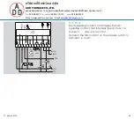
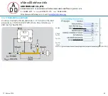
5 .4 .1 TC 116V for valVario controls


The  connection  boxes  of  the  valVario  controls  must  be 

posi-  tioned  on  the  same  side  and  are  connected  via  a 

coupler plug.


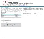
On  a  valve/pressure  regulator  combination,  the 

pressure regulator must be positioned at the outlet.


When  using  valve/pressure  regulator  combination 

VCG/VCV/  VCH,  the valve  can  discharge  the interspace 

pressure  pz  with-  out  the  pressure  regulator  having  to  be 

activated with air during the test period tP.


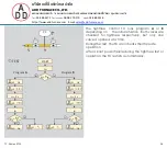
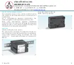
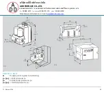
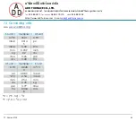
5 .4 .2 TC 4


Install by bolting the lower  section.


The  upper  section  containing  the  detection  circuitry  is  a 

push connection fit into the lower section. For installation 

in  the  control  cabinet  housing,  for  example,  the  lower 

section can      be secured with screws or mounted on a 

DIN rail.


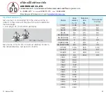
Snap attachment for DIN rails 

Width = 35 mm (1.36 inch).


Summary of Contents for TC

Page 1: ...ce com Tightness control TC Technical Information GB 3 Edition 07 14 AGA Test of two safety valves Short test period thanks to logical decision making in the program sequence Adjustable test period which can be adapted to different systems Adjustable test instant allows quick system start Maximum safety thanks to self monitoring electronics Less space required thanks to small dimensions EU certifi...

Page 2: ...lve for discharge 17 1 1 13 TC 4 in a multiple burner system with two auxiliary valves for supply and discharge 18 1 1 14 TC 4 in a multiple burner system with 3 valves installed in series 19 2 Certification 20 3 Function 21 3 1 Connection diagrams 21 3 1 1 TC 116V for valVario controls VAS VAG and VAD 21 3 1 2 TC 116W 21 3 1 3 TC 2 22 3 1 4 TC 3 22 3 1 5 TC 4 23 3 2 Program sequence 24 3 3 Test i...

Page 3: ...sed in industrial thermoprocessing equipment in boilers and forced draught burners European standards EN 746 2 and EN 676 stipulate tightness controls for capacities over 1200 kW NFPA 86 from 117 kW or 400 000 Btu h in conjunction with a visual indicator Pre purge of the combustion chamber can be dispensed with under certain conditions in accordance with EN 746 2 if a tightness control is used In ...

Page 4: ...0 to 60 C 32 to 140 F TC 4 Tightness control TC 4 consists of detection circuitry and can be installed in the control cabinet separately from the system An external pressure switch takes over the mechanical pressure test between the valves Tightness control TC 4 is independent of gas type and inlet pressure pu and can be used for a test period of up to 10 minutes with a large test volume TC 3 Tigh...

Page 5: ... sales add furnace com TC 1 mounted to a combination control CG TC 2 in a gas inlet section between a quick open ing and a slow opening gas so lenoid valve VG TC 1 on a double solenoid valve in an inlet section TC 3 for tightness control on gas motorized valves VK TC 4 installed in control cabinet by securing the lower section with screws or snapping it on to a DIN rail TC 4 installed sepa rately ...

Page 6: ...valves V1 and V2 for tightness If both valves are tight the tightness control forwards the OK enable signal to the automatic burner control unit GFA This opens valves V1 and V2 simultaneously The burner starts V1 quick or slow opening valve with start rate A Supply and signal forwarding B Automatic burner control unit C Gas solenoid valves PZ Internal pressure sensor of the TC for the comparison o...

Page 7: ... V2 in the combination control for tightness Once the tightness test has been carried out successfully the tightness control forwards the OK enable signal to the automatic burner control unit GFA This opens valves V1 and V2 in the combination control CG simultaneously The burner starts V1 and V2 quick opening valves A Supply and signal forwarding B Automatic burner control unit C Gas solenoid valv...

Page 8: ...ully the tightness control forwards the OK enable signal to the automatic burner control unit GFA The pilot valve output of the automatic burner control unit GFA opens valves V1 and V2 in the combination control simultaneously The burner starts The main valve output opens the two stage valve VZ independently of TC 116W V1 and V2 quick opening valves A Supply and signal forwarding B Automatic burne...

Page 9: ... V1 and V2 for tightness If both valves are tight the tightness control forwards the OK enable signal to the automatic burner control unit GFA This opens valves V1 and V2 simultaneously The burner starts V1 and V2 quick or slow opening valves with start rate A Supply and signal forwarding B Automatic burner control unit C Gas solenoid valves PZ Internal pressure sensor of the TC for the comparison...

Page 10: ...ce valve V2 remains closed during the test it can also be a slow opening motorized valve VK Once the tightness test has been carried out successfully the tightness control forwards the OK enable signal to the automatic burner control unit GFA The pilot valve output of the automatic burner control unit GFA opens the gas solenoid valves V1 and V3 simultaneously The main valve output opens gas soleno...

Page 11: ...ilot valve output of the automatic burner control unit GFA opens the gas solenoid valves V1 and V2 simultaneously The burner starts A relief line is used to discharge the test volume VP into a safe area Thanks to the installed auxiliary valve V3 valve V2 can also be a slow opening motorized valve VK V1 quick or slow opening valve with start rate V2 any V3 quick opening nominal size is dependent on...

Page 12: ...of valve V2 is 5 x VP The gas solenoid valve VAS and the pressure switch DGVAS are used to relieve the pressure The pressure switch must be adjusted in such a way so that enough pressure is relieved and no air can get into the pipework Once the tightness test has been carried out successfully the tightness control TC 2 opens the main valves V1 and V2 with the OK enable signal and enables the downs...

Page 13: ... for tightness using the auxiliary valves installed in TC 3 Once the tightness test has been carried out successfully the tightness control forwards the OK enable signal to the automatic burner control unit GFA The pilot valve output of the automatic burner control unit GFA opens valves V1 and V2 simultaneously The burner starts V1 and V2 any A Supply and signal forwarding PZ Internal pressure sen...

Page 14: ...e tightness test is then carried out using an additional auxiliary valve Tightness control TC 3 checks the tightness between the manually resettable valve V1 and gas solenoid valve V2 using the auxiliary valves installed in TC 3 Once the tightness test has been carried out successfully TC 3 forwards the OK enable signal V1 and V2 any A Supply and signal forwarding PZ Internal pressure sensor of th...

Page 15: ...pheric pressure and the volume downstream of valve V2 is 5 x VP The gas solenoid valve VAS and the pressure switch DGVAS are used to relieve the pressure The pressure switch must be adjusted in such a way so that enough pressure is relieved and no air can get into the pipework Once the tightness test has been carried out successfully the tightness control TC 3 opens the main valves V1 and V2 with ...

Page 16: ...V2 for tightness The external pressure switch DG monitors the pressure be tween the two valves Once the tightness test has been carried out successfully the tightness control forwards the OK enable signal to the automatic burner control unit GFA The pilot valve output of the automatic burner control unit GFA opens the gas solenoid valves V1 and V2 simultaneously The burner starts V1 and V2 quick o...

Page 17: ... the test volume VP safely into the combustion chamber or into a safe area Since valve V2 remains closed during the test it can also be a slow opening motorized valve VK If all the gas solenoid valves are tight the tightness control forwards the OK enable signal to the automatic burner control unit GFA The pilot valve output of the automatic burner control unit GFA opens the gas solenoid valves V1...

Page 18: ...al pressure switch DG monitors the pressure be tween the gas solenoid valves V1 V2 and the burner valves Once the tightness test has been carried out successfully TC 4 opens gas solenoid valve V1 The tightness control forwards the OK enable signal simultaneously to the automatic burner control units for the burner valves The burner valves open and the burners start Thanks to the relief line and au...

Page 19: ...atmospheric pressure The gas solenoid valve VAS and the pressure switch DGVAS are used to relieve the pressure The pressure switch must be adjusted in such a way so that enough pres sure is relieved and no air can get into the pipework Once the start is checked If the pressure downstream of V2 is correct the VAS closes and the tightness test is started Once the tightness test has been carried out ...

Page 20: ...nt standards Electromagnetic Compatibility Directive 2004 108 EC in conjunction with the relevant sections of IEC 801 relating to radiation as well as EN 50093 FM approved TC 1 TC 2 and TC 3 for 120 V and 230 V TC 4 for 24 V 120 V and 230 V Factory Mutual Research Class 7411 Safety overpressure slam shut valves Designed for applications pursuant to NFPA 85 and NFPA 86 www approvalguide com UL list...

Page 21: ...1 and 12 3 1 1 TC 116V for valVario controls VAS VAG and VAD The connection boxes of the valVario controls must be positioned on the same side and are connected via a single coupler plug as shown A Supply and signal forwarding B Automatic burner control unit C Gas solenoid valves 3 1 2 TC 116W A Supply and signal forwarding B Automatic burner control unit C Gas solenoid valves L1 N PE OK L1 V1 L1 ...

Page 22: ... com 3 1 3 TC 2 A Supply and signal forwarding B Automatic burner control unit C Gas solenoid valves wired as shown 1 neutral conductor N blue 2 mains voltage to burner side valve LV2 brown 3 mains voltage to inlet valve LV1 black 3 1 4 TC 3 A Supply and signal forwarding L1 N PE OK 1 2 3 4 5 6 7 8 9 10 11 12 A OK 1 2 TEST TC 3 pu pz pd pu V1 V2 L1 N PE OK L1 V1 L1 V2 1 2 3 4 5 6 7 8 9 10 11 12A 1...

Page 23: ... 08 170 170 แฟกซ 02 888 3258 https www add furnace com E mail sales add furnace com 3 1 5 TC 4 Fault signalling contact on terminals 8 and 9 signalling contact not internally fused max 1 A for 264 V max 2 A for 120 V Connect the NO contact on the pressure switch to terminals 6 and 7 1 2 TEST OK 1 2 3 4 5 6 7 8 9 10 11 12 13 max 1 A PZ 264V pu 2 L1 V1 L1 V2 OK V2 V1 L1 N 5AT ...

Page 24: ...inlet pressure pu 2 valve V2 is OK V2 opens for the fixed opening time tL of 2 s and the test vol ume is discharged V2 closes again During the measurement time tM the TC checks the pressure pZ between the valves again If the pressure pZ is now less than half the inlet pressure pu 2 valve V1 is also OK Program B If the pressure pZ is less than half the inlet pressure pu 2 valve V1 is OK V1 opens fo...

Page 25: ...tightness control TC runs program A or B depending on the initial situation Both valves are checked for tightness respectively but only one valve is opened at a time During the test the TC also checks their fail safe operation After a brief power failure during the tightness test or operation the TC restarts automatically PZ V1 pu 2 V2 pu pZ TEST START tW Program A pZ pu Program B 2 V2 OK V1 OK V2...

Page 26: ... at the factory The test period tP is set using the second jumper right see page 30 Test period tP 3 3 1 Testing before burner run Mode 1 Mains voltage L1 is switched on Once the start up signal has been applied the tightness test starts If the valves are tight the green OK LED lights up The OK enable signal is forwarded to the automatic burner control unit If the tightness control TC detects a le...

Page 27: ... tightness test runs when the voltage L1 is applied If the valves are tight the green OK LED lights up The OK enable signal is not forwarded to the automatic burner control unit until the start up signal has been applied Once the start switched off the tightness test after burner run begins The OK enable signal is not forwarded to the automatic burner control unit again until the start If the tigh...

Page 28: ...258 https www add furnace com E mail sales add furnace com 3 4 Power failure An external fault signal is forwarded by the tightness control and one of the two red LEDs on the TC lights up to indicate a leak on valve V1 or valve V2 After a power failure the external fault signal remains active Both red LEDs are now lit Once a tightness test has been carried out again the TC detects the leaking valv...

Page 29: ...ightness control TC 4 Click on the picture The animation can be controlled using the control bar at the bottom of the window as on a DVD player Toplay the animation you will need Adobe Reader 7 or a newer version If you do not have Adobe Reader on your system you can download it from the Internet Go to www adobe com click on Adobe Reader at the bottom of the page and follow the instructions If the...

Page 30: ...the TC It is set using the second jumper on the unit see page 26 3 6 1 Leakage rate VL It is possible to check a specific leakage rate VL using the TC Within the scope of the European Union the maximum leak age rate VL is 0 1 of the maximum flow rate Qmax m3 h n Qmax m3 h n x 1000 Test instant Leakage rate VL l h 1000 The required test period tP is calculated from Inlet pressure pu mbar Leakage ra...

Page 31: ...ge 32 Calculation example Test volume VP for TC 410 10 is almost arbitrary thanks to the adjustable max test period tP of 600 s L VP VV L x VR Valves Valve volume VV l Nominal size DN Pipe volume VR l m VG 10 0 01 10 0 1 VG 15 0 07 15 0 2 VG 20 0 12 20 0 3 VG 25 0 2 25 0 5 VG 40 VK 40 0 7 40 1 3 VG 50 VK 50 1 2 50 2 VG 65 VK 65 2 65 3 3 VG 80 VK 80 4 80 5 VG 100 VK 100 8 3 100 7 9 VK 125 13 6 125 ...

Page 32: ...example 2 valves VAS 665 DN 65 distance L 9 5 m 31 2 ft inlet pressure pu 50 mbar 20 WC max flow rate Qmax 200 m3 h 7062 SCFH Leakage rate VL l h 200 m3 h x 1000 200 l h 52 8 gal h 1000 Valve and pipe volumes see page 31 Test volume VP Test volume VP l 1 1 l 9 5 m x 3 3 l m 32 45 l 8 44 gal Test period tP s 4 x 50 x 32 45 1 36 45 s 200 Set the next highest value 40 s with the jumper see page 26 Te...

Page 33: ...ies Max test volume VP TC 3 see page 34 Project planning information 4 2 Type code Code Description TC Tightness control 1 For attachment to valVario controls and CG 2 For quick opening individual valves 3 For quick or slow opening or manually resettable individual valves 4 For control cabinet installation 1 Testing before or after burner run 0 External pressure switch required 6 6 mm 0 24 connect...

Page 34: ...scharged via auxiliary valves if dis charge into the furnace chamber is impossible for process reasons 5 1 Selecting the auxiliary valves Selecting auxiliary valve V1 Values for VP and pu see page 32 Calculation example 20 50 VP 32 45 l 8 44 gal 40 30 10 8 20 6 5 4 1 10 10 2 20 30 40 50 80 100 200 300 500 1000 2000 4000 6000 pu 50 mbar 19 5 WC selected The valve is sufficiently large to vent the p...

Page 35: ...w rate Qmax up to 12 l 3 12 gal test volume VP 10 of maximum flow rate Qmax 5 3 Installation Installation position TC 1 to TC 3 in the vertical or horizontal position front panel must not point upwards or downwards Installation position TC 4 any 5 4 Determining the relief line size The nominal diameter of the relief line should be large enough to discharge the test volume VP The cross section of t...

Page 36: ...lve pressure regulator combination the pressure regulator must be positioned at the outlet When using valve pressure regulator combination VCG VCV VCH the valve can discharge the interspace pressure pz with out the pressure regulator having to be activated with air during the test period tP 5 4 2 TC 4 Install by bolting the lower section The upper section containing the detection circuitry is a pu...

Page 37: ...Vario controls For VAS 1 3 For VCS 6 9 An adapter plate is required to attach the tightness control to the right or left hand side of the gas solenoid valve VAS 1 3 Scope of delivery A 1 adapter plate B 2 O rings C 2 retaining screws For attachment to left hand side Order No 74922391 right hand side Order No 74921995 An adapter plate is required to attach the tightness control to the double soleno...

Page 38: ...hes DG DG C for monitoring the pressure between the valves to be checked For inlet pressures of 0 5 to 500 mbar 0 2 to 195 WC The switching differential may not exceed 10 of the set switching pressure see Technical Information bulletin Pressure switch for gas DG DG C at www docuthek com 6 2 1 Adjustment The external pressure switch is set to half the inlet pressure pu 2 only NO contact required in...

Page 39: ...ating cycles Relay outputs 250 000 pursuant to EN 298 Reset button 1000 Housing made of impact resistant plastic TC 1 3 For natural gas town gas and LPG gaseous also for biologi cally produced methane Inlet pressure pu 10 to 500 mbar 3 9 to 195 WC Test period tP 10 to 60 s adjustable Set at the factory to 10 s TC 3 power consumption of the installed valves during the opening time tL max 9 5 VA W E...

Page 40: ...วงศำลำธรรมสพน เขตทวีวัฒนำ กรุงเทพฯ 10170 โทร 02 888 3472 โทร ออกแบบ 08 08 170 170 แฟกซ 02 888 3258 https www add furnace com E mail sales add furnace com 7 1 Indicators and operating controls TEST TEST phase yellow OK Operating signal green 1 Fault valve 1 red 2 Fault valve 2 red Reset button TC 1 3 TC 4 ...

Page 41: ...0 170 แฟกซ 02 888 3258 https www add furnace com E mail sales add furnace com 6 A C B Pg11 78 A Pg 11 78 Pg11 3 07 3 07 8 115 pu 0 24 pZ 65 2 56 115 4 53 C ca 2 m approx 6 ft 0 3 Rp NPT pu pZ 65 2 56 4 53 TC 1 TC 2 7 2 Dimensions 7 2 1 TC 1 TC 2 A Supply and signal forwarding B Automatic burner control unit C Gas solenoid valves pu pe Inlet pressure pu pz Interspace pressure pz B ...

Page 42: ...3472 โทร ออกแบบ 08 08 170 170 แฟกซ 02 888 3258 https www add furnace com E mail sales add furnace com A Pg 11 78 70 3 07 2 76 ø5 0 2 pZ pu Rp NPT pd 115 4 53 pZ 65 28 113 4 45 2 56 1 10 52 75 2 95 2 05 pu pZ TC 3 33 1 30 pd 57 2 24 TC 4 7 2 2 TC 3 TC 4 A Supply and signal forwarding pu pe Inlet pressure pu pz Interspace pressure pz pd pa Outlet pressure pd ...

Page 43: ...ฟกซ 02 888 3258 https www add furnace com E mail sales add furnace com 7 3 Converting units see www adlatus org SI unit multiplier USunit m3 h 35 31 CFH mbar 0 014 5 psi mbar 0 39 WC mm 0 039 inch kg 2 2 lbs litres 0 26 gal m s 3 28 ft s US unit multiplier SI unit CFH 0 028 3 m3 h psi 68 89 mbar WC 2 54 mbar inch 25 4 mm lbs 0 45 kg gal 3 79 litres ft s 0 304 8 m s C F 32 5 9 F C 9 5 32 ...

Page 44: ... a year 9 Legend pu 2 Half the inlet pressure pz Interspace pressure L1 Voltage Start up signal TEST Test phase OK Ready for operation Safety interlocks Limits 1 Fault gas valve V1 2 Fault gas valve V2 Fault signal Gas valve Air valve Flame signal Reset Input signal Output signal tP Testperiod tW Waiting time tL Opening time 2 s tM Measurement time The interspace pressure is the pressure between t...

Reviews: