FCU 500, FCU 505 · Edition 02.17
105
Parameters
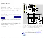
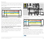
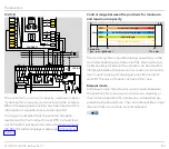
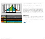
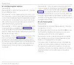
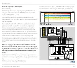
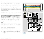
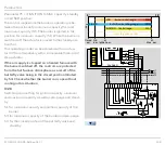
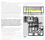
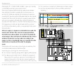
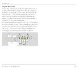
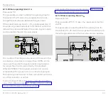
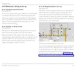
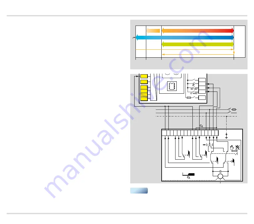
Parameter 75 = 3: IGNITION to MAX. capacity; standby
in CLOSED position.
The control range while the burner is operating is be-
tween the positions for minimum capacity (S1) and
maximum capacity (S3). The burner is ignited in the
position for minimum capacity (S1). When the burner is
switched off, the actuator is moved to the closed posi-
tion (S4).
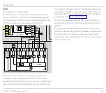
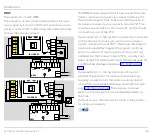
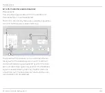
This operating mode can be achieved with an actua-
tor IC 20 or alternatively with a comparable three-point
step actuator.
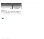
If the air supply is stopped on a heated furnace with
the burner switched off, the controls are protected
from the hot furnace atmosphere as a result of the
butterfly valve being in the closed position (limited
by S4) . Check whether the burner can cope without
cooling in this situation .
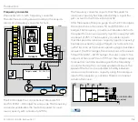
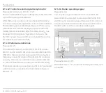
IC 20
Switching cam setting for ignition capacity, minimum
and maximum capacity as well as pre-purge and stand-
by:
S1: for minimum capacity and ignition capacity of the
burner.
S3: for maximum capacity of the burner and pre-purge.
S4: for the closed position of the butterfly valve and
standby.
0°
90°
S4
S1
S3
Move to ignition position
Burner control range
CLOSED
IGNITION
Butterfly valve setting range
Control range
Ignition pos.
Max. pos.
OPEN
Min.
pos.
Closed
pos.
MIN
MAX
MAX
PE
L1
N
3 2 1
16
6
7
4
8
12 11
15
13
S3
S4
S11
S10
0°
90°
M
IC 20
PE
S1
S2
90°
➔
0°
0°
➔
90°
S1
Min
Max
Y-
Y+
1
2
3
46
47
48
49
50
4
67
44
52
45
51
65
66
68
41
42
16
17
18
57
13
14
15
53
54
55
56
58
62 61
5 6 7 8
11 12
FCU 500..F1
5AT
3,15AT
µC
24V
DC
88
▼

