FCU 500, FCU 505 · Edition 02.17
108
Parameters
12 .5 Valve check
12 .5 .1 Valve proving system
Parameter 51
Parameter 51 is used to define whether and at what
time in the FCU program sequence the valve check is
activated. This allows either the tightness of the gas
solenoid valves and the pipework between them to be
checked (tightness test) or the closed position of a so-
lenoid valve (proof of closure function) to be checked.
If the proof of closure function is activated, the closed
position of the gas solenoid valve on the inlet side is
checked using a POC switch.
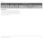
Parameter 51 = 0: Off. No valve check is activated.
Parameter 51 = 1: tightness test before start-up.
Parameter 51 = 2: tightness test after shut-down. With
this setting, a tightness test is also performed after a
fault is reset and after mains on.
Parameter 51 = 3: tightness test before start-up and
after shut-down.
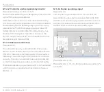
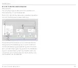
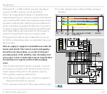
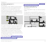
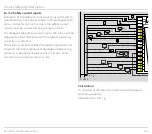
An additional bypass/relief valve must be fitted in
gas sections with an air/gas ratio control, see also
page 108 (Relief valve (VPS)). The valve allows the
closed air/gas ratio control to be bypassed during the
tightness test.
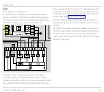
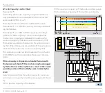
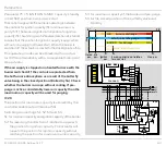
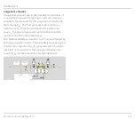
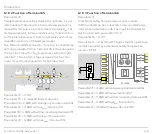
Parameter 51 = 4: proof of closure function (POC).
PZL
PZH
BCU 570..C1
µC
P
49
13
14
50
47
58
48
TC
PZL
PDZ
M
>750°
ϑ
1
2
3
V1
V2
45
GZL
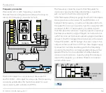
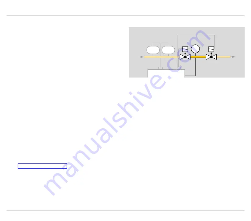
A signal is sent to the FCU via the POC switch on the
gas solenoid valve on the inlet side before burner start-
up stating that the valve is closed. After burner start-up,
the signal must drop out to indicate to the FCU that the
valve is open.
12 .5 .2 Relief valve (VPS)
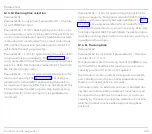
Parameter 52
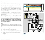
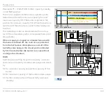
One of the valves connected to terminal 14, 15 or 57
can be selected to discharge the test volume during a
tightness test.
Parameter 52 = 2: V2. The test volume is discharged via
the valve connected to terminal 14.
Parameter 52 = 3: V3. The test volume is discharged via
the valve connected to terminal 15.
Parameter 52 = 4: V4. The test volume is discharged via
the valve connected to terminal 57.

