FCU 500, FCU 505 · Edition 02.17
128
Project planning information
With this circuit design, the function “Contactor feed-
back” at terminal 68 must be activated by setting pa-
rameter 73 to 1.
Before sending the pick-up signal to the contactors via
terminal 57, the FCU checks whether there is a signal at
the check signal input (terminal 68). If there is a signal,
the FCU issues the safety enable signal via terminal 57
to the connected burner control units. The contact
change is checked by the FCU, depending on the out-
put signal of terminal 57 (safety interlocks). If the FCU
detects a malfunction, a fault lock-out will occur with
fault message 37.
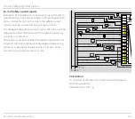
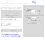
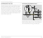
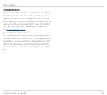
14 .5 .2 BCU with power supply for valves and ignition
transformer via safety interlocks
PE
s
s1
88
c1
F1
230V~
v1
c2
v2
max. 2 A,
253 V
V1 V2
C
N
S
µC
L
l
30 31 32 33 34 35 36 37 38 50 51
l
F3
40 41 42 43 44 45 46 47
1 2
5
6
11
9 10
12 13 14 15
18 19 20
26 27
22
8
7
PE
Z
I
V1
V2
P
L1 (L1)
N (L2)
DI
Test
L1
BCU 460
N1
N1
N1
N1
O
I
ϑ
3 4
16 17
n
max. 2 A,
253 V
A
23
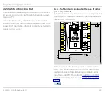
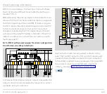
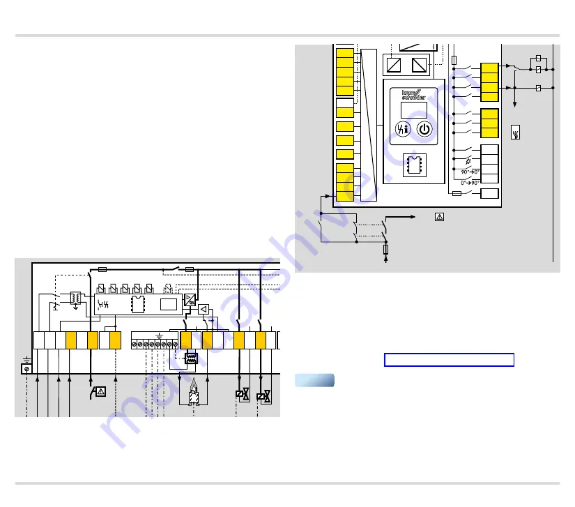
In the event that a higher output current is required, the
output current can be increased by means of a contact
multiplier using 3 contactors.
K3
k3
K1
k1
k1
k3
k2
k2
L1
1
2
3
46
47
48
49
50
4
67
44
52
45
51
65
66
68
41
42
16
17
18
57
13
14
15
53
54
55
56
58
62 61
5 6 7 8
11 12
STW/
STB
N
+24 V
L1
FCU
+ - + -
5AT
3,15AT
µC
24V
DC
88
K2
Input BCU
terminal 5
Input BCU
terminal 22
P
F = I
N
× 0.6
Use contactors with forced-guided contacts in this
case. The two NC contacts of K1 and K2 in series and
parallel to them the NO contact of K3 are connected
to the safety interlock check signal input (terminal 68).
The contacts must be protected with a factor of
≤ 0.6 x I
N
, see page 122 (Safety current inputs).
▼

