FCU 500, FCU 505 · Edition 02.17
17
Function
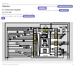
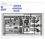
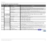
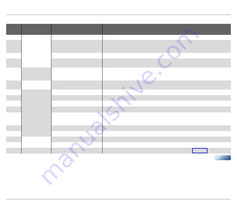
3 .1 .3 Assignment of connection terminals
Terminal
Type
Designation
Function
1
24 V DC input
Start-up signal
Signal applied: FCU start; no signal: FCU stop
2
Controlled air flow
Signal applied: fan is started to supply air to the combustion chamber for cooling, for
example. Only functional in standby. The function is deactivated as soon as a signal is
received at terminal 1 (FCU start).
3
Remote reset
Input for external signal (button) to reset the unit after a fault lock-out
4
Operating signal
Signal from the burner control units to inform the FCU that a sufficient number of burners is
available for temperature control
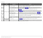
5, 6
and
7, 8
Double
thermocouple
Safety temperature monitor and/or
safety temperature limiter
Monitor the spontaneous ignition temperature of the gas/air mixture in High temperature
mode and/or the maximum furnace or flue gas temperature using the integrated
temperature module of the FCU..H1
11, 12
V AC input
Supply voltage
Voltage to operate the FCU,
11 = phase (L1), 12 = neutral conductor (N)
13
Safety circuit output
Gas valve V1
Connection of phase for gas valve V1
14
Gas valve V2
Connection of phase for gas valve V2
15
Gas valve V3
Connection of phase for gas valve V3
57
Safety interlocks (limits)
Safety enable signal to the burner control units
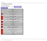
16
Safety limits (limits during start-up)
To ensure that the correct air volume is available for ignition (start fuel flow rate) when
starting the burners, the FCU sends the burner start enable signal to the burner control
units via this output.
17
Purge
Signal to FCU 505 or burner control units to inform them that purge is in process
18
High temperature operation
Enable signal from the FCU indicating that the furnace system is in High temperature mode
41
24 V DC output
Fault
Fault signalling output, 24 V DC, max. 0.1 A
42
Operating signal
Operation signalling output, 24 V DC, max. 0.1 A
44
24 V DC input
Fan ready for operation
Feedback signal from fan indicating readiness for operation, see Parameter 31
▼

