FCU 500, FCU 505 · Edition 02.17
29
Air control
5 .2 Capacity control
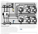
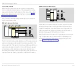
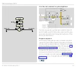
As soon as a start-up signal has been received by the
FCU..F1/F2 (terminal 1), the fan of an FCU 500..F1/F2
is started via terminal 58 after the switch-on delay time
has elapsed. The air volume for pre-purge is requested
via the outputs for central capacity control (terminals
53 to 56). Air flow monitoring (terminal 48) starts. The
pre-purge time starts if there is adequate air flow.
After the elapse of the pre-purge time, the air volume
for ignition is requested. After the program has ended
(limits during start-up, pre-purge and also tightness
test for FCU..C1), the gas enable signal is issued via the
valve outputs V1 (terminal 13) and V2 (terminal 14) and
the burner start enable signal is issued to the burner
control units via the “safety interlock” output (termi-
nal 57).
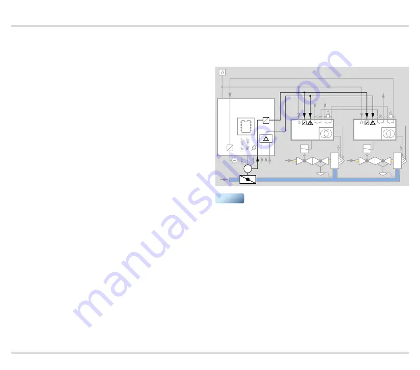
The correct air volume for ignition (start fuel flow rate)
must be available for each burner start, restart or start-
up attempt. To this end, the FCU sends the burner start
enable signal to the BCUs via the “LDS (limits during
start-up)” output.
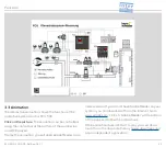
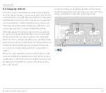
A corresponding circuit design between the FCU and
the BCUs ensures that the burners can only start if the
safety interlocks and the LDS output are active.
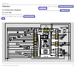
BCU
V1
BCU
V1
FCU 500..F1
µC
54 55
53
1
67
(BCU..F0)
+24V
L1
4
M
16
57
M
16
57
▼

