FCU 500, FCU 505 · Edition 02.17
42
Valve proving system
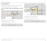
7 .1 .4 Two test volumes for system tightness
PZL
PZH
FCU 500..C1
µC
P
49
15
13
14
50
47
58
48
TC
PZL
PDZ
M
>750°
ϑ
1
2
3
p
u
/2
PZ
V
p1
V
p2
V1
V2
45
V3
p
u
p
Z
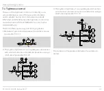
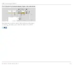
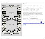
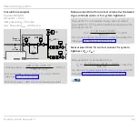
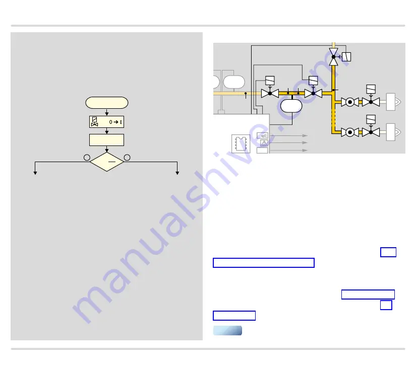
The test volumes V
p1
and V
p2
(gas solenoid valves V1
and V2, relief valve V3, the burner valves and the pipe-
work) are checked to test the system tightness of the
entire gas inlet section.
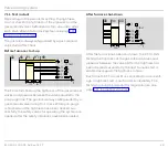
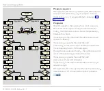
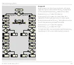
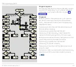
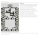
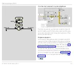
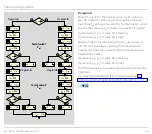
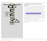
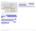
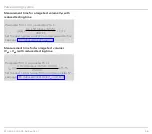
Program sequence
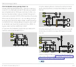
At the start of the tightness test, the relief valve V3 is
opened to reduce the pressure of the test volume V
p2
to around atmospheric pressure. The opening time for
V3 can be defined using parameter 55, see page 110
(Opening time relief valve V3). The tightness con-
trol queries the pressure p
Z
using the external pres-
sure switch to check the first test volume. If pressure
p
Z
> p
u
/2, program A starts, see page 43 (Program A).
If pressure p
Z
< p
u
/2, program B starts, see page 44
tL = P59
tM = P56
+
–
tL = P59
tM = P56
pZ >
pu
2
+
–
V2
OK
pZ >
pu
2
V1
OK
V1
V2
OK
V1
V1
V1
OK
V2
V2
V2
V1
V2
pZ >
pu
2
+
–
pZ >
pu
2
+
–
tL = P59
tM = P56
V1
V1
tL = P59
tM = P56
V2
V2
pZ >
pu
2
+
–
tL3 = P55
V3
Vp2 OK
Vp1
OK
pZ >
pu
2
+
–
tL = P59
tM = P57
V1
V2
V3
V1
Vp2
Program
A
Program
B
Program
A
Program
B
Vent V
p2
Test of valve 1
V
p1
Test of valve 2
V
p1
Test of valve V3
and
burner-side
valves
V
p1
+ V
p2
Wait for 1 s
END
START
▼

