FCU 500, FCU 505 · Edition 02.17
49
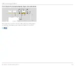
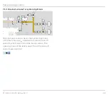
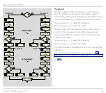
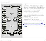
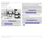
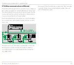
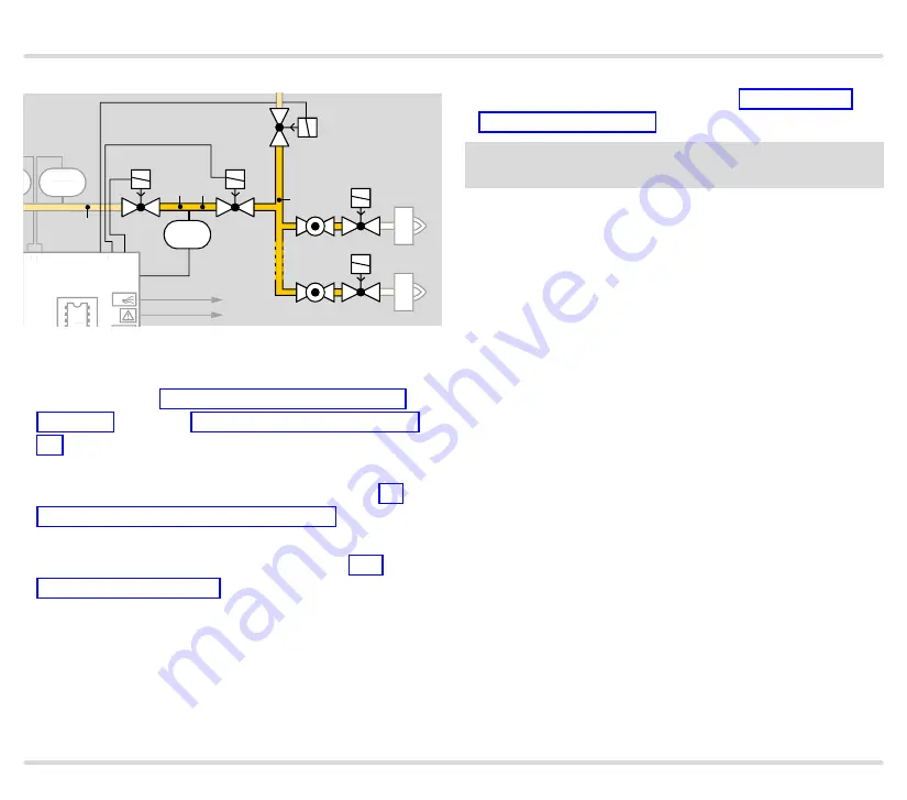
Valve proving system
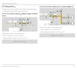
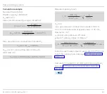
7 .2 .3 For two test volumes for system tightness (V
p1
+ V
p2
)
PZL
PZH
FCU 500..C1
µC
P
49
15
13
14
50
47
58
48
TC
PZL
PDZ
M
>750°
ϑ
1
2
3
p
u
/2
PZ
V
p1
V
p2
V1
V2
45
V3
p
u
p
Z
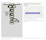
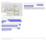
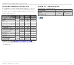
The test period t
P
is calculated from:
– Opening time of relief valve V3 to reduce the pressure
of V
p2
, see page 42 (Two test volumes for system
tightness) and page 110 (Opening time relief valve
V3),
– Opening times t
L
for V1 and V2 to check the test vol-
ume V
p1
and test volumes V
p1
+ V
p2
, see page 42
(Two test volumes for system tightness),
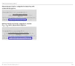
– Measurement times t
M
for V1 and V2 to check the
test volume V
p1
(parameter 56), see page 110
– Waiting time 1 s,
– Measurement time t
M
to check the test volumes
V
p1
+ V
p2
(parameter 57), see page 110 (Measure-
t
P
[s] = t
L3
+ 3 x t
L (P59)
+ 2 x t
M(P56)
+ t
M(P57)
+ 1


