FCU 500, FCU 505 · Edition 02.17
61
Fieldbus communication via Ethernet
9 .2 Configuration, planning
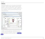
Before commissioning, the bus module must be config-
ured for data exchange with the fieldbus system using
an engineering tool or BCSoft.
To do so, fieldbus communication must be activated on
the control unit with connected bus module BCM and
the code switches on the BCM set, see also page 118
(Fieldbus communication).
9 .2 .1 Profinet/Device master data file (GSD)
In addition to cyclic data exchange, Profinet also pro-
vides acyclic data exchange for events which are not
constantly repeated such as sending device statistics.
In the event that the bus communication is faulty or
interrupted and during initialization of the bus com-
munication after switching on, the digital signals are
interpreted as “0”.
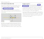
The technical properties of a device are described by
the manufacturer in a device master data file (GSD file).
The GSD file is required for integration of the device
(BCU/FCU) in the configuration of the PLC. The GSD
file contains the device image, the communications
properties and all fault messages from the device in
text form which are important for the configuration of
the Profinet network and the data exchange. Modules
defined in the GSD file may be selected for configura-
tion to integrate the device. The GSD file for the bus
module can be ordered at www.docuthek.com. The
steps required to integrate the file are described in the
instructions for the engineering tool for your automa-
tion system.
9 .2 .2 Modbus TCP
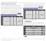
The Modbus protocol is a communications proto-
col based on a Client/Server architecture. Once the
TCP/IP connection between client (PLC) and server
(BCU/FCU) has been established, useful data can be
transferred via this connection as often and in as great
an amount as required. The PLC and BCU/FCU can es-
tablish up to 3 parallel TCP/IP connections at the same
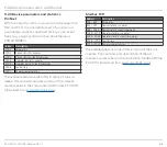
time. Using the function codes 3, 6 and 16, data can be
transferred to and from the BCU/FCU.
The PLC must send output data to the BCU/FCU at
least every 125 ms in order to ensure data transfer and
functioning of the BCU/FCU. If the output data is miss-
ing or sent too late, the bus module will interpret them
as “0”.

