FCU 500, FCU 505 · Edition 02.17
94
Parameters
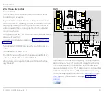
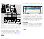
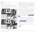
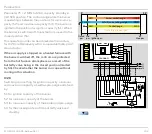
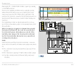
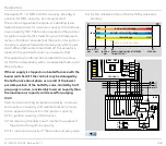
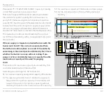
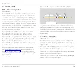
IC 40
Parameter 40 = 2: with IC 40
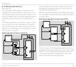
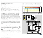
The interface is configured according to the require-
ments of actuator IC 40 with an optional analogue in-
put. Operating mode 27 must be parameterized on the
IC 40 to ensure communication with the FCU.
N
0 V
IC 40
PE
19 18
16 15 14
12 11 10
8 7
5 4
2 1
A
AC
D
DC
M
mA
L N
22 21 20
R..
1
2
3
46
47
48
49
50
4
67
44
52
45
51
65
66
68
41
42
16
17
18
57
13
14
15
53
54
55
56
DI 1
DI 2
58
62 61
5 6 7 8
11 12
STW/
STB
P
HT
+24 V
L1
V1
V2
V3
LDS
0,6 × I
N
FCU 500..F1
+ - + -
5AT
3,15AT
µC
24V
DC
88
K2
K1
k11 k21
I
N
× 0,6
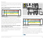
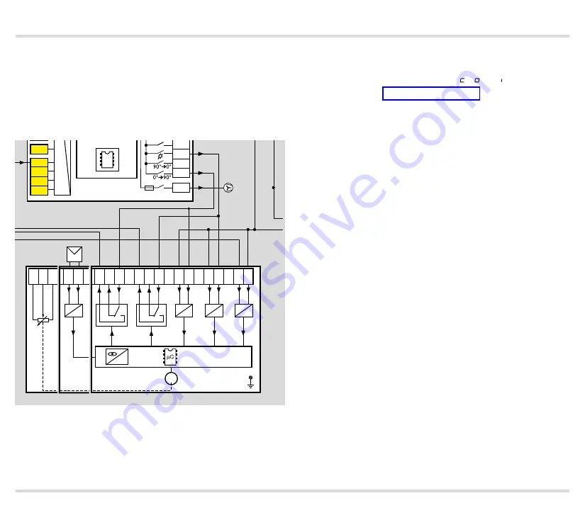
The positions for maximum capacity and ignition
capacity can be set using the actuator. Terminal 51
checks whether the position for maximum capacity has
been reached. Terminal 52 checks the position for igni-
tion capacity. If the position is not reached within the
timeout time of 255 s, a fault lock-out of the FCU will
be performed. A fault message (
A
,
A
or
A
) will be dis-
played, see page 70 (Fault signalling).
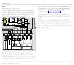
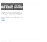
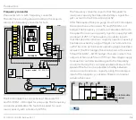
If a controller enable is active, the control system is
enabled for operation via the outputs at terminals 53
and 55.
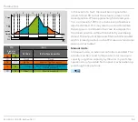
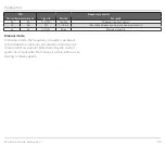
During the controller enable procedure, the actuator
IC 40 can be adjusted infinitely between the positions
for maximum and minimum capacity using its ana-
logue input (terminals 18 and 19). There is no timeout
active in this case.

