FCU 500, FCU 505 · Edition 02.17
98
Parameters
Frequency converter
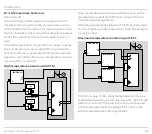
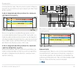
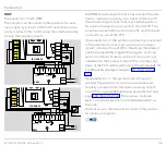
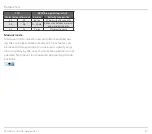
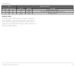
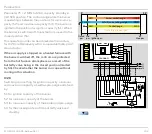
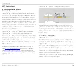
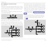
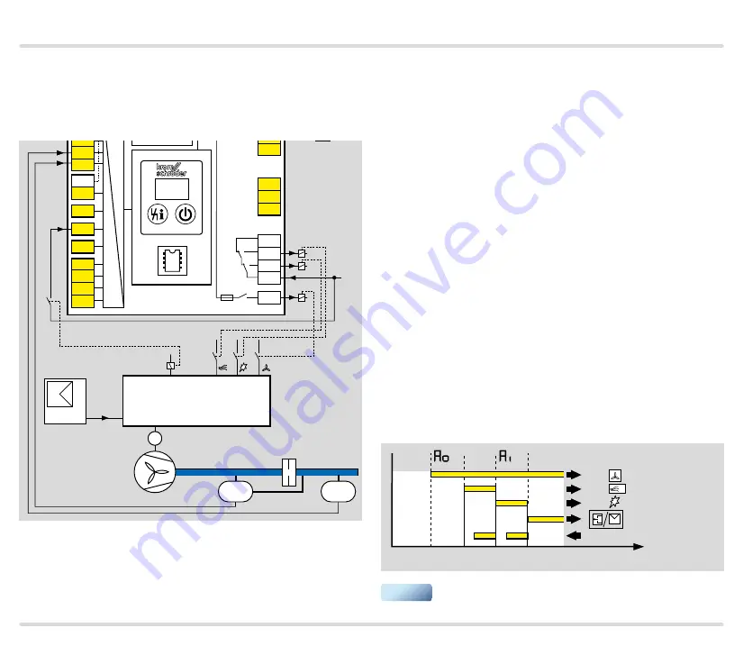
Parameter 40 = 4: with frequency converter
The interface is configured according to the require-
ments of a frequency converter for fans.
mA
PZ
PDZ
M
L1
FU
DI 3
DI 2
DI 1
P
0–100%
COM
HI
LO
AUTO
1
2
3
47
48
4
67
44
52
45
51
65
66
68
41
42
16
17
18
57
13
14
15
53
54
55
56
58
62 61
5 6 7 8
11 12
STW/
STB
N
P
HT
A
ϑ
0 V
FCU 500..F2
+ - + -
K2
K1
k11 k21
I
N
× 0,6
5AT
3,15AT
µC
24V
DC
88
PLC
Target = actual
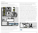
The FCU bridges the connections at terminals 53
and 54 (COM – HI bridge) for pre-purge. The frequency
converter accelerates the fan to the speed for maxi-
mum capacity with a timeout of 255 s.
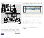
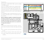
The frequency converter reports that the speed for
maximum capacity has been reached by a signal (tar-
get = actual) to the FCU via terminal 52.
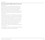
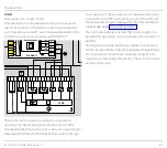
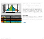
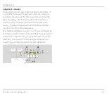
After the elapse of the pre-purge time, the FCU bridges
the connections at terminals 53 and 55 (COM – LO
bridge). The frequency converter accelerates the fan to
the speed for minimum capacity (ignition capacity) with
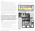
a timeout of 255 s. The frequency converter reports
that the speed for minimum capacity (ignition capacity)
has been reached by a signal (target = actual) via termi-
nal 52. As soon as the burner operating signal has been
received, the FCU bridges the connections at terminals
53 and 56 (COM – AUTO bridge). This disconnects the
outputs at terminals 54 and 55 from the voltage supply
to issue the controller enable signal to the frequency
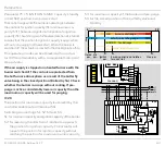
converter. During the controller enable procedure, the
speed of the fan can be adjusted infinitely between
minimum and maximum capacity using the analogue
input of the frequency converter. There is no timeout
active in this case.
P
P1
00
08
58
54
55
52
t
mA
Controller enable
Target = actual
▼

