FCU 500, FCU 505 · Edition 02.17
127
Project planning information
14 .5 Safety interlock output
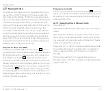
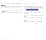
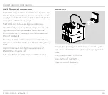
The burner start enable signal is issued to the connect-
ed burner control units via the safety interlock output
(terminal 57).
For units whose safety interlock input has a current
consumption of ≤ 2 mA, the available power (max. 0,5 A,
cos
ϕ
= 1) of the FCU is sufficient to directly activate the
burner control units.
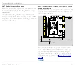
14 .5 .1 Safety interlock output in the case of higher
power requirement
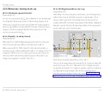
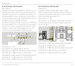
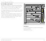
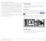
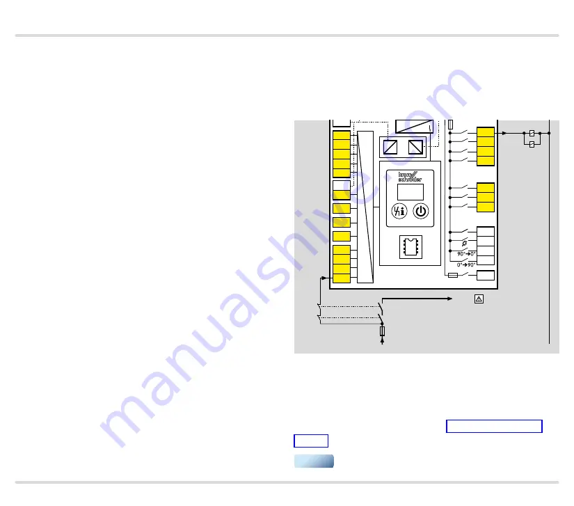
In the event that a higher output current is required, the
output current can be increased by the additional con-
nection of 2 contactors.
K1
K2
k1
k1
k2
k2
L1
1
2
3
46
47
48
49
50
4
67
44
52
45
51
65
66
68
41
42
16
17
18
57
13
14
15
53
54
55
56
58
62 61
5 6 7 8
11 12
STW/
STB
N
+24 V
L1
FCU
+ - + -
5AT
3,15AT
µC
24V
DC
88
Input
automatic burner control unit
F = I
N
× 0.6
Use contactors with forced-guided contacts in this
case. The two NC contacts in the contactors are con-
nected in series to the safety interlock check signal
input (terminal 68); the contacts must be protected
with a factor ≤ 0.6 x I
N
, see page 122 (Safety current
▼

