FCU 500, FCU 505 · Edition 02.17
129
Project planning information
Before sending the pick-up signal to the contactors K1
and K2 via terminal 57, the FCU checks whether there is
a signal at the check signal input (terminal 68). If there
is a signal, the FCU issues the safety enable signal via
terminal 57 to the connected burner control units. The
contact change is checked by the FCU, depending on
the output signal of terminal 57 (safety interlocks). If
the FCU detects a malfunction, a fault lock-out will oc-
cur with fault message 37.
The function “Contactor feedback” can be activated by
setting parameter 73 to 1.
14 .6 Actuators
If actuators are used, the start gas rate of the burners
must be limited for SIL 3 applications in compliance
with the standard.
14 .6 .1 IC 20
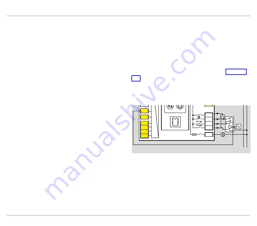
The FCU..F1 checks the position to which the actuator
IC 20 has moved using terminal 52 (feedback) by lifting
the signal to terminal 53, 54 or 55, see page 146 (Lift-
ing).
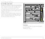
To ensure this check is possible, FCU..F1 and actuator
IC 20 must be wired as shown in the connection dia-
gram.
1
2
34
6
47
48
49
50
4
67
44
52
45
51
65
66
68
41
42
16
17
18
57
13
14
15
53
54
55
56
58
62 61
5 6 7 8
11 12
N
0 V
FCU 500
+ - + -
5AT
3,15AT
µC
24V
DC
88
M
STW/
STB
14 .7 Air control
Starting the fan with the butterfly valve closed reduces
the start-up current of the fan motor.

