III - 7
Operation
3.7 Cutter unit
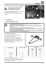
3.7.1 Special safety instructions
The following applies during all maintenance, assembly, repair and adjustment work:
•
Shut down the short-cut feeder wagon.
•
Shut down the engine, remove the ignition key and switch off the electrical supply at the
control box.
•
Secure the tractor and short-cut feeder wagon against rolling away.
•
When installing and removing the cutter, there is a high risk of injury from cuts. Only handle
the cutter while wearing suitable gloves.
•
The cutter is installed and removed from underneath the loading wagon. Always support the
short-cut feeder wagon on the secured stabilising foot.
3.7.2 General information
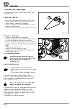
The cutter unit has 39 individual cutters which are
protected against foreign objects.
Either 0, 19, 20 or 39 cutters can be switched in,
according to choice, via the central cutter switch.
The cutters are arranged in on level. Theoretically, the
shortest cutting length is 40 mm. Longer lengths can be
achieved by swinging the cutter sets away using the
central adjustment (see Table).
The cutter unit has a hydraulic cutter-
0-system, so that if there are any blockages, the cutter
can be swung out of the conveyor channel hydraulically
via the control unit on the tractor.
Cutting length
Number of cutters
cutter unit
Set
front (1)
Set
rear (2)
-
0
off
off
~ 80 mm
19
on
off
~ 80 mm
20
off
on
~ 40 mm
39
on
on
KDW00031
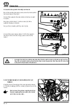
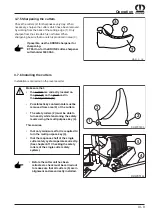
3.6.1 Roll-type crop guard
(Special Equipment)
The roll-type crop guard is an accident
preventing device and must not be
removed during field operation.
When handling bis swaths the roll-type crop guard (1) can
be adjusted to match the crop density.
For this the chains (2) must be attached in a higher
position.
XXL00001
Summary of Contents for 4XL-RGD
Page 4: ...Foreword ...
Page 10: ...I 4 General information ...
Page 15: ...II 5 Safety ...
Page 22: ...II 12 Safety ...
Page 64: ...VI 18 Maintenance ...
Page 66: ...VII 2 Overwintering ...
Page 68: ...VIII 2 Recommissioning ...
Page 70: ...IX 2 Faults causes and removal ...
Page 80: ...A 10 Appendix Operator friendlyoperation A2 Electrical circuit diagram ...
Page 81: ...A 11 Appendix ...
Page 82: ...A 12 Appendix ...
Page 83: ...A 13 Appendix ...


