background image

Settings


42 


Pos: 27.7 /Überschriften/Überschriften 2/A-E/E/Entl astungsfeder n einstell en @ 387\mod_1445259926661_78.docx @ 2774908 @ 2 @ 1 


9.2 

Setting the Relief Springs  

Pos: 27.8 /BA/Sicher heit/7. Gefahrenhi nweise alt/Mähwer ke/Gefahr - Einstell ung an den Entlastungsfedern @ 0\mod_1196751594562_78.docx @ 12575 @  @ 1 


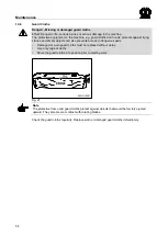
Danger! - Setting on the compensation springs 

Effect: Danger to life or serious injuries 
•  The compensation springs must only be removed in transport position. In the working 

position the compensation springs are subject to high tensile stress. 

•  Severe injury can be caused if the compensation springs are removed while in the working 

position. 

•  The lower threaded blocks on the compensation springs must be fully screwed in. 


Pos: 27.9 /BA/Einstell ung en/Mähwer ke/EasyC ut/Bodendruck/Bodendruck allgemeiner T ext all e EC @ 0\mod_1196667271181_78.docx @ 10190 @  @ 1 


The ground pressure for the cutter bar is adjusted to local conditions by means of the 

compensation springs. In order to protect the sward the load on the mowing spar must be 

relieved so that it does not jump when mowing, yet does not leave any skid marks on the 

ground. 

Pos: 27.10 /BA/Ei nstellungen/M ähwer ke/M ähwer ke AM  Baur eihe/Einstell en der Entlastungsfeder(n) Bild AM-S Baur eihe @ 69\mod_1305107338880_78.docx @ 634201 @  @ 1 


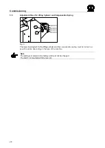
AMS-0-051


Fig. 19 

Pos: 27.11 /BA/Ei nstellungen/M ähwer ke/M ähwer ke AM  Baur eihe/Hi nweis Die Federn ( 2) und (3)  entl asten den Mähhol m an der Außens eite. @ 73\mod_1308228901018_78.docx @ 655316 @  @ 1 


Note 

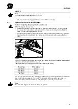
Springs (2) and (3) relieve the cutter bar on the outside. 


Pos: 27.12 /BA/Ei nstellungen/M ähwer ke/M ähwer ke AM  Baur eihe/Einstell en der Entlastungsfeder(n) T ext AM-S Baurei he @ 69\mod_1305106937483_78.docx @ 634174 @  @ 1 


•  Bring the machine into the transport position 
•  Close the shut-off valve on the hydraulic cylinder 
•  Remove the compensation springs (2,3) in the transport position of the 

disc mower from the 

top retaining bolt (1) 

•  Turn the upper adjustment pieces to change the length 
 

The further the adjustment pieces are screwed in, the greater the relief on the mowing 
unit.  


•  After the setting is made, attach the compensation spring on the retaining bolt again and 

secure it with a washer (6) and cotter pin (7) 


Pos: 27.13 /BA/Ei nstellungen/M ähwer ke/M ähwer ke AM  Baur eihe/Hi nweis bei zwei Entlastungsfedern beide gl eich ei nstellen @ 69\mod_1305107374613_78.docx @ 634228 @  @ 1 


Note 

In disc mowers with two compensation springs, the two compensation springs must be set to 

the same length. 


Pos: 27.14 /Layout Module  /---------------Seitenumbr uch---------------- @ 0\mod_1196175311226_0.docx @ 4165 @  @ 1 

Summary of Contents for AM 203 S

Page 1: ...Original operating instructions Disc Mower AM 203 S AM 243 S AM 283 S AM 323 S from serial no 829 190 Order no 150 000 002 02 us 12 09 2016 ...

Page 2: ...Table of Contents 2 Pos 2 Layout Modul e Seitenumbruch 0 mod_1196175311226_0 docx 4165 1 ...

Page 3: ... 4 4 Attached devices 14 4 5 PTO operation 14 4 6 Hydraulic system 15 4 7 Maintenance 15 4 8 Unauthorised Conversion Modification and Spare Parts Production 15 4 9 Inadmissible Modes of Operation 15 4 10 Working in the vicinity of power transmission lines 16 4 11 Introduction 17 4 12 Position of the Adhesive Safety Stickers on the Machine 18 4 13 Position of the General Information Labels on the M...

Page 4: ...read 46 10 3 2 Metric Thread Screws with Fine Thread 47 10 3 3 Metric Thread Screws with Countersunk Head and Hexagonal Socket 47 10 3 4 Tightening Torques for Locking Screws and Bleed Valves on the Gearboxes 48 10 3 5 Deviating Tightening Torques 49 10 4 Filling Quantities and Lubrication Designations for Gearboxes 50 10 4 1 Oil Level Check and Oil Change Intervals Gearboxes 50 10 5 Main gearbox ...

Page 5: ...Special Safety Instructions 66 13 2 Test run 66 13 3 Friction Clutch 68 13 4 Walterscheid Overload Coupling 68 14 Special equipment 69 14 1 Special Safety Instructions 69 14 2 Adjusting Skids 69 15 Disposal of the machine 70 15 1 Disposal of the machine 70 16 Index 71 Pos 5 Layout Modul e Seitenumbruch 0 mod_1196175311226_0 docx 4165 1 ...

Page 6: ...04546850246_78 docx 70549 1 Note In the operating instructions which follow the disc mower will also be referred to as the machine Pos 6 4 BA Vor wortBeachten Si e für M aschine 450 mod_1462780469180_78 docx 3064205 1 Please note The operating instructions are part of your machine Only operate this machine after you have been trained to do so and according to these instructions It is essential to ...

Page 7: ... Baur eihe 69 mod_1305029359144_78 docx 630919 1 The disc mower is used for cutting crops growing on the ground Pos 8 4 BA Ei nleitung Mähwer ke AM Baurei he Gültig kei t AM 203S 243S 283S 323S 69 mod_1305029444025_78 docx 630947 2 1 3 2 Validity These operating instructions apply to disc mowers of series AM 203 S AM 243 S AM 283 S and AM 323 S Pos 8 5 Ü berschriften Ü berschriften 3 A E A Ansprec...

Page 8: ...507505930_78 docx 126110 2 1 3 4 Information Required for Questions and Orders Year Mach No Type Note The entire identification plate represents a legal document and should not be altered or rendered illegible When asking questions concerning the machine or ordering spare parts be sure to provide type designation machine number and the year of manufacture of the relevant machine To ensure that the...

Page 9: ...these operating instructions After each season of use the machine must be checked thoroughly for wear and other damage Damaged and worn parts must be replaced before placing the machine into service again After the machine has been used for five years carry out full technical inspection of the machine According to the results of this inspection a decision concerning the possibility of reuse of the...

Page 10: ...Pos 10 Layout M odul e Di ese Seite ist bewusst freig elassen worden 1 mod_1201783680373_78 docx 54443 1 This page has been left blank deliberately Pos 11 Layout M odul e Seitenumbruch 0 mod_1196175311226_0 docx 4165 1 ...

Page 11: ...714 2 1 4 2 Identification of the hazard warnings Danger DANGER Type and source of the hazard Effect Danger to life or serious injuries Measures for hazard prevention Warning WARNING Type and source of the hazard Effect Injuries serious material damage Measures for hazard prevention Caution CAUTION Type and source of the hazard Effect Property damage Measures for risk prevention Pos 13 4 BA Sicher...

Page 12: ...re not respected this could result in the forfeiture of any claims for damages Failure to follow the safety instructions could result for example in the following hazards Endangering of persons due to not protected working areas Breakdown of important machine functions Failure of prescribed methods for repair and maintenance Endangering of persons due to mechanical and chemical effects Damage to t...

Page 13: ...vided 13 Observe permitted axle loads gross weight and transport dimensions 14 Check and attach transport equipment such as lighting warning devices and protective equipment 15 Actuating mechanisms cables chains linkages etc for remote controlled devices must be positioned in such a way that no movements are unintentionally triggered in any transport or working positions 16 Ensure that implements ...

Page 14: ...ing coupling on the implement side 6 Always make sure that the PTO shaft is properly installed and secured 7 Attach chains to prevent the PTO shaft guard from rotating with the shaft 8 Before switching on the PTO make sure that the selected PTO speed of the tractor matches the permissible implement speed 9 Before switching on the PTO shaft make sure that no person is in the danger zone of the devi...

Page 15: ... tractor side 2 Observe the safety clearance behind the machine In normal operation the safety distance is 5m Observe the safety clearance laterally to the machine It is 3 m in normal operation Pos 13 6 15 BA Sicherheit Wartung Wartung Pos 2 bis 8 ohne Elektroni k 73 mod_1308295728779_78 docx 655465 1 3 Regularly check that nuts and bolts are properly seated and tighten if necessary 4 When perform...

Page 16: ...f approx 4m 3 If there is any need to travel under overhead lines the machine operator must request information on the rated voltage and the minimum height of the overhead lines from the overhead line operator 4 Always keep the safety distances according to the table Rated voltage kV Safe distance from overhead lines m To 1 1 Above 1 to 110 2 Above 101 to 220 3 Above 220 to 380 4 Pos 13 8 Layout M...

Page 17: ... unl esbar e Warnbildzeichen 120 mod_1343305789479_78 docx 1099853 1 WARNING Danger of injury on machine parts if danger zones have not been marked when warning pictograms are missing damaged or illegible Danger of injury due to dangerous parts and other residual risks as users or third parties enter the danger area or reach into it as they are not aware of the danger Immediately replace damaged o...

Page 18: ...esive Safety Stickers on the Machine Pos 13 13 BA Sicherheit Aufkleber AM Mähwer keSicherheitsaufkl eber AM 203S 243S 283S 323S US 404 mod_1448953456930_78 docx 2867506 1 2 5 8 7 4 3 6 1 6 9 Fig 2 1 CAUTION Max PTO speed 540 RPM 27 004 600 0 Order No 27 004 600 0 1x 2 Order No 27 002 055 0 2x 3 Order No 27 002 060 0 1x 4 CAUTION 27 002 059 0 Order No 27 002 059 0 1x ...

Page 19: ...ator to run equipm ent Do not operate equipm ent in trans port pos ition Never lubricatem adjust unclog or service the equipment with trac tor engine is running Wait for all movement to stop before opening shield or servicing m ac hine Nev er work underneath equipm ent without s ec urely s upporting Order No 27 002 054 0 1x 6 Warning 27 002 057 0 To avoid personal injury Never put your hand into t...

Page 20: ...A Sicherheit Aufkleber AM Mähwer ke Hi nweisaufkl eber AM 203S 243S 283S 323S 69 mod_1305033327671_78 docx 631092 1 5 1 6 3 2 4 Fig 3 1 139 888 0 139 889 0 80 139 888 139 889 939 567 1 1x 2 939 180 2 1x 3 939 541 2 1x AM 203 S 939 542 2 1x AM 243 S 939 546 2 1x AM 283 S 939 545 2 1x AM 323 S 4 942 132 0 1x 5 15 mm min 3mm 942 009 2 1x with blade screw connection 5 18mm 12mm 939 548 0 939 548 0 1x ...

Page 21: ... Effect Adhesion of label The attachment area must be clean dry and free from dirt oil and grease Pos 13 18 Ü berschriften Ü berschriften 3 A E A Anspr echpartner KRON E NORTH AMER ICA 10 mod_1221053854903_78 docx 131870 3 1 4 13 3 Contact for KRONE NORTHAMERICA Pos 13 19 BA Adr essenAdr esse KRON E N orth America 417 mod_1453355357015_78 docx 2921495 1 Mailing address Krone North America Inc P O ...

Page 22: ... 15 Layout M odul e Di ese Seite ist bewusst freig elassen worden 1 mod_1201783680373_78 docx 54443 1 This page has been left blank deliberately Pos 16 Layout M odul e Seitenumbruch 0 mod_1196175311226_0 docx 4165 1 ...

Page 23: ...us injuries or death Switch off tractor engine remove the ignition key and carry it with you Secure the tractor against accidental start up and against rolling Wait until all machine parts have come to a complete stop and have been cooled down completely Pos 17 7 BA Sicher heit 7 Gefahrenhi nweise alt Gefahr Fehler hafter Zusammenbau 1 mod_1202224212591_78 docx 58171 1 Danger Incorrect assembly Ef...

Page 24: ...at II AMS 1 001 Fig 4 Pos 17 14 BA Erstinbetriebnahme M ähwer ke AM Baurei he a Kat II Kuppelpunkte Text AM S und AM C V Baurei he 69 mod_1305036909040_78 docx 632644 1 a Cat II The standard setting of the steerable pinions is for Cat II Pos 17 15 BA Erstinbetriebnahme M ähwer ke AM Baurei he Kuppelpunkte Bild AM S Kat I 73 mod_1308144145546_78 docx 655231 1 b 2 1 Kat I AMS 0 040 Fig 5 Pos 17 16 B...

Page 25: ...e c Kat II seitlich versetzt AM S und AM C V Baur eihe 69 mod_1305037661078_78 docx 632692 1 c Cat II offset to the side To offset the mower to the side for Cat II turn the steerable pinion 3 180 and shift the steerable pinion 1 outwards Remove the screws 2 Insert the steerable pinion 3 rotated 180 Offset the steerable pinion 1 outwards Tighten the screws 2 again Pos 17 20 Layout Module Seitenumbr...

Page 26: ...uring transport or work If the lower suspension arms 1 are equipped with catch hooks the following items must be taken into consideration Especially in the headland position high forces develop in the lower suspension arm bolts 3 that act upwards in the left hand hook For this reason the catch hooks must be in a flawless condition Additionally the catch hooks must be secured in the provided lockin...

Page 27: ...bes Shorten section tubes and guard tubes so that the universal shaft can move freely in the shortest operating position For further procedure please refer to the operating instructions of universal shaft manufacturer Pos 17 30 BA Sicherheit Gel enkwell e Achtung Schwenkber eich Freir aum über prüfen 9 mod_1220536308930_78 docx 126898 1 Caution Swivel range of the PTO shaft Effect Damage to the tr...

Page 28: ...Verstellstück Aushubzyli nder Entlastungsfeder Verstellstück Aushubzyli nder Entl astungsfeder Text 72 mod_1307514666785_78 docx 651420 1 The lower bearing bolt for the lifting cylinder and the compensation spring must be locked in a specific position depending on the type of the machine Pos 17 36 BA Inbetri ebnahme M ähwer ke AM Baureihe Verstellstück Aushubzyli nder Entlastungsfeder Hi nweis Ei ...

Page 29: ...his reason the catch hooks must be in a flawless condition Additionally the catch hooks must be secured in the provided locking hole 4 against unwanted opening after the machine has been connected to the tractor Pos 19 4 BA Sicher heit 7 Gefahrenhi nweise alt Mähwer ke Warnung Achsl asten Beei ntr ächtigung der Lenkfähig keit 9 mod_1220866555985_78 docx 128119 1 Warning Impairment of the steerabil...

Page 30: ...fy the hydraulic connections Always ensure correct connection between the machine and the tractor When engaging the hydraulic hose the hydraulic control unit must be in float position or in lowering position Pos 19 13 BA Sicherheit H ydr auli k Achtung Verschmutzung der H ydrauli kanlag e 2 mod_1202393336803_78 docx 59155 1 Caution Soiling of the hydraulic system Effect Damages to the machine When...

Page 31: ...o the machine This machine may only be driven with a max PTO speed of 540 rpm Before switching on the PTO make sure that you have selected the correct PTO speed Pos 19 22 BA Sicherheit Gel enkwell e Achtung Schwenkber eich Freir aum über prüfen 9 mod_1220536308930_78 docx 126898 1 Caution Swivel range of the PTO shaft Effect Damage to the tractor or the machine Check the swivel range and clearance...

Page 32: ...sition The lower threaded blocks on the compensation spring s must be fully screwed in Pos 19 27 4 BA Inbetri ebnahme M ähwer ke AM Baur eihe Entlastungsfeder Hi nweis Die hi ntere Entlastungsfeder kann nur in Transportstellung der Maschi ne monti ert werden 69 mod_1305095664117_78 docx 633029 1 Note The rear compensation spring can only be mounted in the transport position of the machine Pos 19 2...

Page 33: ...port Absperrhahn Transport Str aßenfahr t Absperr hahn schließen Schutz ei nrasten EC 280 320 10 mod_1221540227604_78 docx 134129 1 Danger Transport road travel Effect Danger to life serious injuries or serious damage to the machine In transport position always close the hydraulic shut off valve Always make certain that the lock 1 has snapped into place Pos 21 4 Überschriften Überschriften 2 U Z V...

Page 34: ...mowing unit lifts up into the transport position Lower the lock 2 Closing the Hydraulic Shut Off Valve 3 on the Hydraulic Cylinder 4 Note Locked position of the shut off valve hand lever 90 in the direction of the line Pos 21 9 Überschriften Überschriften 2 A E BBeleuchtung 0 mod_1195658399935_78 docx 1881 2 1 7 2 Lighting Pos 21 10 BA Fahr en und Transpor t Mähwer ke AM Baur eihe Bel euchtung Bil...

Page 35: ...Gefahrenhi nweise alt Mähwer ke Gefahr Verrieg elung pr üfen EC 280 320 9 mod_1220879526173_78 docx 128463 1 Danger Check whether the locking mechanism 1 is folded down completely Effect Danger to life serious injuries or serious damage to the machine The folded down locking mechanism secures the mowing unit against inadvertent lifting while the machine is running Pos 23 5 BA Bedi enung Mähwer ke ...

Page 36: ...maged worn or missing replace them if necessary Pos 23 10 BA Bedienung EasyC ut Hi nweis Bei m M ähen Steuer ventil schwi mmstellung senken 9 mod_1220881412391_78 docx 128661 1 Note While mowing Effect Proper use of the machine Leave control unit s in the Lower or Float position position for work Pos 23 11 Ü berschriften Ü berschriften 3 P T SSchutzeinrichtung her unter kl appen 9 mod_122088107907...

Page 37: ...schriften 2 U Z VVorgewendestellung 0 mod_1196414916041_78 docx 8116 2 1 8 4 Headland Position Pos 23 17 BA Sicherheit Vorg ewendestell ung Gefahr Vorgewende M ähwer ke EC 280 320 9 mod_1220881723360_78 docx 128683 1 Danger Lifting the mowing unit from the working position into headland position Effect Danger to life injuries or damage to the machine Lift the mowing unit into headland position onl...

Page 38: ...se to and disconnecting it from the hydraulic system of the tractor the tractor system as well as the machine system must be depressurised Move the appropriate control valves into the flow position When detaching the machine do not walk between the tractor and the machine Pos 23 22 BA Sicherheit 7 Gefahr enhinweise alt Einstell arbeiten Einstell ungen Gefahr Einstell ung an den Entlastungsfedern n...

Page 39: ...ng M ähwer ke AM Baurei he Absperr ventil öffnen 69 mod_1305103778536_78 docx 633753 1 Open the shut off valve on the hydraulic cylinder 2 of the disc mower see dotted item To lower the mowing unit pull up the lock from the tractor using the actuating rope Activate the double action control valve on the tractor to slowly lower the mowing unit Disconnect the hydraulic hose from the tractor set the ...

Page 40: ...s 25 Layout M odul e Di ese Seite ist bewusst freig elassen worden 1 mod_1201783680373_78 docx 54443 1 This page has been left blank deliberately Pos 26 Layout M odul e Seitenumbruch 0 mod_1196175311226_0 docx 4165 1 ...

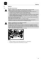
Page 41: ...t rolling away Pos 27 3 Überschriften Überschriften 2 A E EEinstell en der Schnitthöhe 0 mod_1196660879619_78 docx 9191 2 1 9 1 Adjusting the cutting height Pos 27 4 BA Einstell ung en Mähwer ke Schni tthöhe Schnitthöhe Bild AM 203S 243S 283S 323S 69 mod_1305104693672_78 docx 633836 1 Fig 18 Pos 27 5 BA Einstell ung en Mähwer ke Schni tthöhe Schnitthöhe größer_g eringer AM 203S 243S 283S 323S 69 m...

Page 42: ...e M ähwer ke AM Baur eihe Einstell en der Entlastungsfeder n Bild AM S Baur eihe 69 mod_1305107338880_78 docx 634201 1 AMS 0 051 Fig 19 Pos 27 11 BA Ei nstellungen M ähwer ke M ähwer ke AM Baur eihe Hi nweis Die Federn 2 und 3 entl asten den Mähhol m an der Außens eite 73 mod_1308228901018_78 docx 655316 1 Note Springs 2 and 3 relieve the cutter bar on the outside Pos 27 12 BA Ei nstellungen M ähw...

Page 43: ...ransport position even with abrupt loads Pos 27 20 BA Ei nstellungen M ähwer ke EasyCut Pfahlsicher ung Pfahlsicherung Bil d AM 203S 243S 283S 323S 69 mod_1305105171394_78 docx 634013 1 Fig 20 Pos 27 21 BA Ei nstellungen M ähwer ke EasyCut Pfahlsicher ung Pfahlsicherung allgemein 9 mod_1220961293021_78 docx 130429 1 In order to protect the disc mower against damages during driving over obstacles i...

Page 44: ...2260_78 docx 17199 2 1 9 5 Adjustable throttles Pos 27 30 BA Ei nstellungen Dr ossel Drossel ei nstellen Bil d AM S Baur eihe 72 mod_1307360563456_78 docx 647256 1 AMS 0 015 1 Fig 22 Pos 27 31 BA Ei nstellungen Dr ossel Drossel 1 Aushubgeschwi ndigkeit Arbeits i n Vorgewendestellung 11 mod_1223455172960_78 docx 146790 1 Throttle 1 Throttle 1 adjusts the lifting speed from working position to headl...

Page 45: ...ays replace missing and damaged blades in sets to prevent unbalanced rotation Never mount unevenly worn blades on a drum disc Whenever a blade is changed also inspect the fasteners and replace them if necessary Pos 29 5 Überschriften Überschriften 3 P T PPr obel auf 0 mod_1196833698843_78 docx 15023 3 1 10 1 1 Test run Pos 29 6 BA Sicher heit 7 Gefahrenhi nweise alt Mähwer ke Gefahr Probel auf Ein...

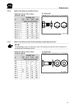
Page 46: ... egelgewinde Tabelle 321 mod_1424760222607_78 docx 2477725 1 NOTICE The table does not apply to countersunk screws with hexagonal socket in case the countersunk screw is tightened via hexagonal socket Tightening torque in Nm unless otherwise stated A thread size stability class can be seen on screw head A Stability class 5 6 8 8 10 9 12 9 Tightening torque Nm M4 3 0 4 4 5 1 M5 5 9 8 7 10 M6 10 15 ...

Page 47: ...10 7 Ü berschriften Ü berschriften 3 K O MM etrische Gewindeschrauben mit Senkkopf und Innensechskant 323 mod_1424945970760_78 docx 2484818 3 1 10 3 3 Metric Thread Screws with Countersunk Head and Hexagonal Socket Pos 29 10 8 BA Wartung Drehmomente Anziehdrehmomente Anziehdrehmomente Metrische Gewi ndeschr auben mi t Senkkopf un d Innensechskant Tabelle 321 mod_1424843938347_78 docx 2480155 1 NOT...

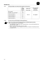
Page 48: ...ehdr ehmomente Verschl ussschr auben an Getrieben_Tabell e 454 mod_1464167170747_78 docx 3083045 1 This table applies only to locking screws with external hex in connection with copper seal ring for bleed valves made of brass with shaped seal ring Thread Locking screw and viewing glass with copper ring Ventilation breather filter made of steel Bleed valve made of brass Ventilation and breather fil...

Page 49: ...s Pos 29 14 BA War tung Drehmomente AnziehdrehmomenteAbweichendes Anzi ehdrehmoment AM S Baur eihe 468 mod_1470300437282_78 docx 3165731 1 AM 5 066 1 2 3 Fig 23 Screws nuts Tightening torque Bearing housing for cutting disc 1 55 Nm Clamping pot screw 2 210 Nm Bearing housing for mower drum 3 55 Nm Pos 29 15 Layout Module Seitenumbr uch 0 mod_1196175311226_0 docx 4165 1 ...

Page 50: ...ter bar AM 203 S 4 0 l Cutter bar AM 243 S 5 0 l Cutter bar AM 283 S 6 0 l Cutter bar AM 323 S 7 0 l Pos 29 18 BA War tung Zei tinter valle an den Getrieben 200 h 0 mod_1196951919921_78 docx 15373 3 1 10 4 1 Oil Level Check and Oil Change Intervals Gearboxes Note Oil level check and oil change gearboxes and lubricating the machine Effect Long expected service life of machine First oil change on al...

Page 51: ... Gearboxes Unscrew the inspection screw 1 Oil level up to bore hole 1 If necessary top up the oil SAE 90 Screw the check screw 1 back in Pos 29 20 5 BA Wartung Öl kontroll e_Wechsel Öl wechsel_ALT Ölwechsel Version1 Bel üftungsfilter 0 mod_1197010026283_78 docx 15747 1 Oil change For time intervals see Chapter Oil Level Check and Oil Change Intervals Gearboxes Screw out the screw plug 2 Collect th...

Page 52: ...197008973815_78 docx 15649 1 Oil level check For time intervals see Chapter Oil Level Check and Oil Change Intervals Gearboxes Unscrew the inspection screw 1 Oil level up to bore hole 1 If necessary top up the oil SAE 90 Screw the check screw 1 back in Pos 29 22 6 BA Wartung Öl kontroll e_Wechsel Öl wechsel_ALT Ölwechsel Version1 Bel üftungsfilter 0 mod_1197010026283_78 docx 15747 1 Oil change For...

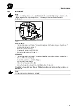
Page 53: ...g discs blade drums continue to run Do not leave the driver s cab until the cutting discs blade drums have come to a complete stop Pos 29 24 7 BA Sicherheit 6 Überar beitete Warnhinweise Hinweis Ver weis auf Anziehdrehmomente Verschlussschr auben 469 mod_1470667868238_78 docx 3167926 1 Note Tighten the locking screws on the gearboxes with the prescribed tightening torques refer to chapter Maintena...

Page 54: ... Use only original cloths Move the guard cloths into position prior to starting work Pos 29 28 BA War tung Mähwer ke AM Baur eihe Schutztücher AM S Bild 70 mod_1305119375958_78 docx 635034 1 Fig 27 Pos 29 29 BA War tung Mähwer ke AM Baur eihe Hinweis D er Schutzrahmen und di e Schutztücher schützen vor hochgeschleuderten Geg enständen 70 mod_1305119565233_78 docx 635061 1 Note The protective frame...

Page 55: ...d at least once a year To perform maintenance release the tension on the spring 2 and remove it Then pull the pole protection 1 apart and clean the contact surfaces of both inclined bevels Then grease the inclined bevels and mount the pole protection Note For the triggering moment setting see Pole Protection Setting in the Settings chapter Pos 29 33 Layout Module Seitenumbr uch 0 mod_1196175311226...

Page 56: ...per day and check retaining bolts every time you change the blades or after contact with foreign objects Immediately replace missing or damaged cutter blades and cutter blade retainers Pos 29 34 3 BA Wartung Mähwerke Schutzvorrichtung hochklappen runter klappen Bild AM S Baureihe 73 mod_1308125196166_78 docx 655025 1 Fig 29 Pos 29 34 4 BA Wartung Mähwerke Schutzvorrichtung hochklappen runter klapp...

Page 57: ...60_78 docx 2409555 1 Danger Insufficient thickness of material on the cutter blades Effect Danger to life or serious injuries The cutter blades must be replaced at the latest when the wear limit is reached see mark 1 on the cutter blade dimension a less than or equal to 13 mm Pos 29 34 9 BA Wartung Mähwerke M ähklingen beidseitig verwenbar_neu 3 mod_1204728012601_78 docx 72608 1 a EC 253 0 1 Fig 3...

Page 58: ...t the weakest point Fig 31 Pos 29 34 12 BA Wartung M ähwer ke M esserschr aub M esserschnellverschluss M esserschnell verschluss H altebolzen 9mm AM 70 mod_1305178072510_78 docx 635701 3 1 10 10 3 Blade Quick Fit Device DANGER Insufficient thickness of material on the retaining bolts Effect Danger to life or serious injuries Every time a blade is changed check the thickness of the holding bolts ma...

Page 59: ...0 1 Danger Cutter blades coming loose Effect Danger to life or serious injuries After changing the blades check that they fit perfectly and that they can move freely Whenever a blade is changed also inspect the fasteners and replace them if necessary Always replace missing and damaged blades in sets to prevent unbalanced rotation Never mount unevenly worn blades on a drum disc Pos 29 34 17 BA Wart...

Page 60: ... esserschnellverschluss Beschr eibung M esser wechsel M esserschr aubverschl uss Hinweis 71 mod_1306221707374_78 docx 644013 1 Note The cutter blades of anticlockwise rotating cutting discs blade drums are different to those of clockwise rotating ones Make certain the direction of rotation is correct when installing The arrow on the cutter blades must match the direction of rotation of the corresp...

Page 61: ...nellverschluss Beschr eibung M esser wechsel M esserschnellverschluss Hinweis 72 mod_1306223027118_78 docx 644069 1 Note The cutter blades of anticlockwise rotating cutting discs blade drums are different to those of clockwise rotating ones Make certain the direction of rotation is correct when installing The arrow on the cutter blades must match the direction of rotation of the corresponding cutt...

Page 62: ...Effect Damage to the machine Always check the mowing unit for damaged linings prior to start up and replace linings if necessary Adjust the welding current and the welding material to the cutter bar material and to the lining or carry out a trial welding if necessary ART NR 150 039 MH 0 001 Fig 36 Pos 29 35 Layout Module Seitenumbr uch 0 mod_1196175311226_0 docx 4165 1 ...

Page 63: ...e engine of the tractor remove the ignition key and carry it with you Secure the tractor against accidental start up and against rolling After the repair maintenance cleaning work or technical modifications are completed mount all protective covers and safety devices properly again Avoid skin contact with oils greases cleaning agents and solvents In the event of injuries or burns due to oils clean...

Page 64: ...plan 0 mod_1197361829026_78 docx 18495 2 1 11 3 Lubrication Chart Pos 29 36 8 BA Wartung Mähwerke EasyC ut AM Mähwerke Schmier pläne Schmi erplan AM S 70 mod_1305190543492_78 docx 636128 1 AMS 0 013 10 h 10 h 50 h Fig 38 Pos 30 Layout M odul e Seitenumbruch 0 mod_1196175311226_0 docx 4165 1 ...

Page 65: ...e Gel enkstellen einölen 70 mod_1305633347429_78 docx 638432 1 Oil all joint points Pos 31 2 5 BA Einl agerung Lackschäden ausbesser n blanke Stellen gründlich mit R ostschutzmittel konser vi eren 70 mod_1305630900253_78 docx 638320 1 Touch up damaged paint and preserve all uncoated areas thoroughly with rust protection agent Pos 31 2 6 BA Einl agerung Alle beweglichen Bauteile über prüfen 70 mod_...

Page 66: ...After the repair maintenance cleaning work or technical modifications are completed mount all protective covers and safety devices properly again Avoid skin contact with oils greases cleaning agents and solvents In the event of injuries or burns due to oils cleaning agents or solvents contact a physician immediately All other safety instructions must also be followed to avoid injuries and accident...

Page 67: ...n the bearings Check oil level in the gearbox es and top up if necessary Check all screws to make certain they are tight or retighten them if necessary Check all electrical connection cables and the lighting Repair or replace if necessary Check the entire setting of the machine and correct if necessary Re read the operating instructions thoroughly Note Use vegetable oils and greases Pos 31 12 BA E...

Page 68: ...plates If necessary smooth the friction surfaces with emery paper Then attach the PTO shaft again and proceed as described in section Walterscheid Overload Coupling Pos 31 17 BA Inbetri ebnahme EasyCut Hinweis R ei bkupplung 11 mod_1223358975938_78 docx 145593 1 Note Friction Clutch Effect Conserve functionality and increased service life The friction clutch 2 must be vented prior to commissioning...

Page 69: ...rly again Avoid skin contact with oils greases cleaning agents and solvents In the event of injuries or burns due to oils cleaning agents or solvents contact a physician immediately All other safety instructions must also be followed to avoid injuries and accidents Pos 33 4 Überschriften Überschriften 2 F J HH ochschnittkufen 70 mod_1305639862319_78 docx 638598 2 1 14 2 Adjusting Skids Pos 33 5 BA...

Page 70: ... to a metal recycling centre The components must be freed from operating fluids and lubricants gear oil oil from hydraulic system before being scrapped The operating fluids and lubricants must be brought separately to an environmentally friendly disposal point or recycling centre Operating fluids and lubricants Operating fluids and lubricants diesel fuel coolant gear oil oil from hydraulic system ...

Page 71: ...tion Clutch 68 From transport into working position 35 G Gearbox on the carrying bar 52 Guard Cloths 54 H Headland Position 37 Hydraulic system 15 Hydraulics 30 I Identification Plate 8 Identifying Symbols in the Operating Instructions 11 Inadmissible Modes of Operation 15 Information Required for Questions and Orders 8 Install the PTO shaft 31 Intended use 9 Introduction 7 L Lighting 34 Lubricati...

Page 72: ...cial equipment 69 Special Tool 59 Start up 29 Switching from working position to transport position 33 T Technical data 9 Test run 66 Test run 45 Tightening torques 46 Tightening Torques for Locking Screws and Bleed Valves on the Gearboxes 48 U Unauthorised Conversion Modification and Spare Parts Production 15 Using the Machine for Work 37 W Walterscheid Overload Coupling 68 Working in the vicinit...

Page 73: ......

Page 74: ...chinenfabrik Bernard Krone GmbH Co KG Heinrich Krone Straße 10 D 48480 Spelle Postfach 11 63 D 48478 Spelle Phone 49 0 59 77 935 0 Fax 49 0 59 77 935 339 Internet http www krone de eMail info ldm krone de ...

Reviews: