XII - 5
Maintenance - Electrical System
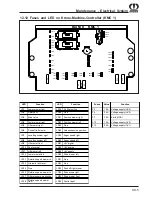
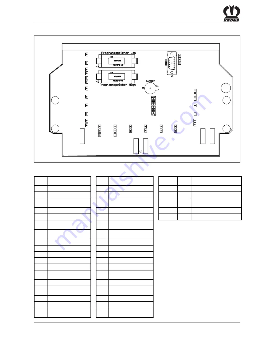
12.12 Fuses and LED on Krone-Machine-Controller (KMC 1)
Big M II KMC 1
LD1
LD2
LD3
LD4
LD5
LD6
LD7
LD8
LD9
LD10
LD11
LD12
LD13
LD14
LD15
LD16
LD17
LD18
LD19
LD20
LD21
LD22
LD23
LD24
LD25
LD26
LD30
LD31
LD32
LD33
LD34
LD35
LD36
LD27
LD28
LD29
F2
F6
F7
LD38
F12
F13
LED
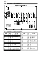
Function
LED
Function
Fuses
Value
Function
LD1
Lower mower front
LD19
Air filter soiling
F2
10 A
Voltage supply (UV4)
LD2
Safety exit
LD20
Free
F6
25 A
Voltage supply (UV2)
LD3
Main valve
LD21
Position mower right
F7
30 A
Earth (GND)
LD4
Lower mower right
LD22
Position mower left
F12
10 A
Voltage supply (UV3)
LD5
Lift mower right
LD23
Free
F13
25 A
Voltage supply (UV1)
LD6
Push off left mower
LD24
Axle suspension position
LD7
Levelling system right
LD25
Auger speed right
LD8
Levelling system left
LD26
Auger speed left
LD9
Lift mower front
LD27
+8V digital
LD10
Fan reversal
LD28
+8V analog
LD11
Lift mower left
LD29
+5V supply
LD12
Lower mower left
LD30
Drive mower left
LD13
Rotation speed mower rh
LD31
Free
LD14
Hydraulic tank level
LD32
Free
LD15
Free
LD33
Push off right mower
LD16
Rotation speed mower lh
LD34
Drive mowe right
LD17
Filter pressure monitoring
LD35
Drive mower front
LD18
Rotation speed mower
front
LD36
Control input
Summary of Contents for Big M II
Page 2: ......
Page 4: ...Vorwort Notizen ...
Page 28: ...II 14 Safety ...
Page 35: ...III 7 Controls 3 7 Roof Console BMII 192 A B A Compartment B Airconditioning heating ...
Page 42: ...III 14 Controls ...
Page 64: ...VI 8 Cabin ...
Page 68: ...VII 4 Check before Start up ...
Page 74: ...VIII 6 Engine Operation ...
Page 100: ...X 20 Mowers 10 6 Front Mower Lubrication Chart EC 087 1 ...
Page 136: ...XII 16 Maintenance Electrical System ...
Page 148: ...XV 4 Belt Drive ...
Page 154: ...A 2 Appendix ...
Page 155: ...A 3 Appendix ...


