background image

VIII - 3

Engine  Operation

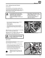
8.6 Starting  Engine

Only start the engine from the operator's

seat.

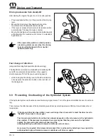
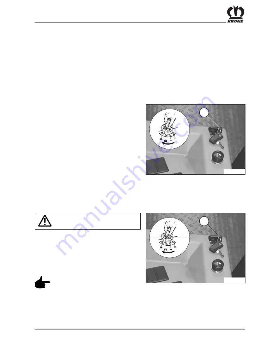
• Turn the starter switch to position II. Release the key

as soon as the engine starts. Never hold the key in the

start position for longer than 20 secs.

If you turn the key switch to position I before the engine

starts, wait until the engine has come to a standstill before

attempting to start again.

If the engine does not start within

20 secs., wait at least 2 min. before

attempting to start again.

BMII-177

1

BMII-177

1

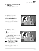
8.5 Switching  On  Ignition

II

-

The ignition is switched on

The following 

indicator lights 

will illuminate:

• Engine failure indicator light (2) for approx. 2 seconds

Job computer carries out internal system check

The basic display appears

Job computer carries out an internal system check.

The standard display appears.

8.4 Switching on the Circuit for the

Electronics

I

-

Circuit for the electronics is switched on

Summary of Contents for Big M II

Page 1: ...Operating Instructions Self propelled High Performance Mower Conditioner Big M II from serial no 502 000 No 880 1 USA ...

Page 2: ......

Page 3: ...igh Performance Mower Conditioner thatthesenotesandinformation are adhered to Please note Always keep this instruction manual behind the passenger seat in the driver s cabin as it is an integral part of your machine Only operate this machine after you have been trained to do so and according to these instructions It is essential to observe the safety instructions It is also necessary to observe th...

Page 4: ...Vorwort Notizen ...

Page 5: ...lic System II 3 2 9 Battery II 3 2 10 Cooling System II 3 2 11 Tyres II 4 2 12 Emergency Exit II 4 2 13 Maintenance II 4 2 14 Unauthorised Modification and Manufacture of Replacement Parts II 4 2 15 Prohibited Modes of Operation II 4 2 16 Safety Instructions on the Machine II 5 2 16 1 Location of Safety Decals on the Machine II 6 2 16 2 Location of General Information Labels on the Machine II 12 3...

Page 6: ... 6 1 6 F2 Select US _ GB Metric IV 6 4 6 1 7 F3 Select language IV 6 4 6 2 Meters F2 IV 7 4 6 2 1 F1 Odometer IV 7 4 6 2 2 F2 Acreage meter IV 7 4 6 2 3 F3 Hour meter IV 8 4 6 3 F3 Manual operation IV 8 4 6 3 1 F1 Cutter bar manual operation IV 8 4 6 3 2 F2 Fan reversal button operation IV 9 4 6 3 3 F3 Axle spring manual operation IV 9 4 6 4 F4 Service IV 9 4 6 4 1 F1 Diagnosis IV 9 4 6 4 2 F2 Kro...

Page 7: ... 18 Emergency Hammer VI 6 6 19 AdjustableAir Nozzles VI 7 7 Check before Start up VII 1 7 1 Daily Checks VII 1 7 2 Soil Deposits in the Engine Bay VII 1 7 3 Engine Oil Level VII 1 7 4 Hydraulic Oil Level VII 1 7 5 Fuel Level VII 2 7 6 Engine Coolant Control VII 2 7 7 After a Long Standstill Period VII 2 7 8 Tyres VII 2 7 9 Checks in the Cabin VII 3 8 Engine Operation VIII 1 8 1 Running In the Engi...

Page 8: ... Swath Width X 8 10 2 10 Setting the transverse link on side mowers X 9 10 2 11 Front mower guiding plates X 9 10 3 Maintenance ot the Mowers X 10 10 3 1 Special Safety Instructions X 10 10 3 2 General X 10 10 3 3 Greasing the Universal Joint Shaft X 11 10 3 4 Required Quantities and Lubricant Designations for Gearboxes X 11 10 3 5 Oil level check and oil change intervals gearboxes X 11 10 3 7 Ang...

Page 9: ...1 13 3 Pressure Relief Valve XI 7 11 13 4 Adjustable Throttles XI 8 11 14 Hydraulic Oil XI 9 11 14 1 List of Mineral Oils for the Hydraulic System XI 9 11 15 Hydraulic oil level XI 10 11 16 Replacing hydraulic oil filter XI 10 11 17 Distribution Transmission XI 11 11 18 Windscreen Washer XI 11 11 19 Checking and Maintaining Tyres XI 12 11 20 Fitting Tyres XI 12 11 21 Wheel Fixing XI 12 12 Maintena...

Page 10: ...of the Coolant XIII 5 13 11 Check the condenser XIII 6 14 Storage XIV 1 XIV 1 14 1 At the End of the Harvest Season XIV 1 14 2 At the End of the Harvest Season Engine XIV 2 14 3 Before the Start of a New Season XIV 2 15 Belt drive XV 1 15 1 Ventilation wheel drive XV 1 15 2 Deployments arms XV 1 15 3 Mower drive XV 2 16 Lubrication chart Periodical Maintenance XVI 1 16 1 Maintenance during the Run...

Page 11: ...tting width to beadapted Integratedmowingconditionersaccelerate the mowing material drying process 1 2 Information on the Product 1 2 1 General Information These operating instructions are valid for the Big M II self propelledhigh performancemower conditionerfrom machine no 502 000 on 1 2 2 Manufacturer s Address MaschinenfabrikBernardKroneGmbH Heinrich Krone Straße10 D 48480Spelle Germany Telepho...

Page 12: ...e Any use of the machine for other purposes is deemed not to be in accordance with specifications The manufacturer shall not be held liable for any damage which results from improper use this is the sole responsibility of the operator Operation in accordance with intended use also includes observingtheoperating maintenanceandservice instructions specified by the manufacturer ...

Page 13: ...Nm 700 Hydrostaticdrivepower LevelI 0 to 17 km h continuously variable 4 wheel drive LevelII 0 to 40 km h continuously variable 4 wheel drive Switchable axle disengagement in level 1 Drivepump max delivery capacity 425 l min max pressure 430 bar Filling quantities Filling quantities I Raffinedoils Bio lubricants Typedescription Typedescription Diesel tank approx 560 seechapter Engine Engine oil ap...

Page 14: ...thtotal individual mm 9720 3140 front 3520 side Transportwidth mm 3000mower Number of mower discs 4 side mower 5 front mower Numberofmowerdrums 4 side mower 2 front mower Conditioningsystem V shaped prong rollers Speedofconditioner rpm 700 1000 ...

Page 15: ...thorised service centres only 2 3 Failure to Follow the Safety Instructions Failure to follow the safety instructions could result in personal injury and environmental hazards as well as damage to the machine Failure to follow the safety instructions could result in the forfeiture of any claims fordamages Failure to follow the safety instructions could result for example in the following hazards r...

Page 16: ...oss weight and transportdimensions 13 Check and attach transport equipment such as lighting warningdevicesandanyprotective equipment 14 Actuating mechanisms cables chains linkages etc for remote controlled devices must be positioned in such a way that no movements are unintentionally triggered in any transport or working positions 15 Ensure that implements are in the prescribed condition for on ro...

Page 17: ...ar of the implement during this time Be sure that the machine has come to a complete stop before starting any maintenance work 2 Disengage the drive stop the engine and remove the ignition key before cleaning lubricating and adjusting the PTO shaft driven implements or the PTOshaft 2 8 Hydraulic System 1 The hydraulic system is pressurized 2 When connecting hydraulic cylinders and engines make sur...

Page 18: ...se suitable tools and gloves 5 Dispose of oils greases and filters according to regulations 6 Always disconnect the power supply before working on the electrical system 7 If protective devices and guards are subject to wear check them regularly and replace them in good time 8 When doing electrical welding on the self propelled highperformancemower conditionerandattached implements disconnect the p...

Page 19: ...uld impair its full functional capability Corresponding danger notices attached to the machine warn against any dangers The safety instructions are provided in the form of so called warning pictograms Important information on the location of these safety signs and what they mean is givenbelow Familiarise yourself with the meaning of these warning signs The text beside them and their location on th...

Page 20: ...II 6 Safety 6 4 5 2 3 7 2 4 5 2 4 3 2 BMII 238 8 BMII 233 6 1 9 2 2 3 1 7 5 4 4 2 5 4 3 8 2 2 16 1 Location of Safety Decals on the Machine left side of the machine right side of the machine ...

Page 21: ...tion Never put your hand into danger area with a risk of crushing as long as the parts are able to move Do not touch moving machine parts Wait until they have come to a complete standstill Move guard into position Do not stand within the slewing range Maintain a safe distance while the engine is running Danger rotating shaft The accumulator is subject to gas and oil pressure Disassemble and repair...

Page 22: ...II 8 Safety 6 4 5 2 3 7 2 4 5 2 4 3 2 BMII 238 8 BMII 233 6 1 9 2 2 3 1 7 5 4 4 2 5 4 3 8 2 left side of the machine right side of the machine ...

Page 23: ...I 9 Safety 9 Order no 942 405 0 1x During repair work welding always turn off the engine Disconnect battery main switch and remove both cable connectors from the unit pump PLD control unit at the engine ...

Page 24: ...II 10 Safety 3 5 6 3 1 BMII 249 4 1 8 7 6 BMII 250 6 3 4 2 3 1 6 left side of the machine right side of the machine ...

Page 25: ... 2 1 Required WARNING 942 032 2 Close valve when transporting or servicing machine 7 949 229 0 1 Required 8 949 228 0 1 Required Thrown objects or blade contact can cause serious injury or death Stay clear of machine while in operation Keep discharge chute and shields in place Replace worn or damaged portective skirting DANGER 942 020 2 ...

Page 26: ...1 1 13 10 18 13 5 7 18 19 14 20 13 13 16 16 10 1 10 1 13 13 1 13 13 1 1 BMII 241 17 19 20 19 14 3 3 17 9 8 8 9 21 22 23 2 16 2 Location of General Information Labels on the Machine left side of the machine right side of the machine ...

Page 27: ...ng 942 379 0 1x 653 long 942 380 0 3x 566 long 942 341 0 1x 893 long beige 942 243 0 2x 1400 long green 942 320 0 1x 600 long beige 942 323 0 1x 775 long green 1000 700 942 240 0 Beide Unterlegkeile nur an der Vorderachse verwenden Use both wheel chocks for the front axle only N utiliser les deux cales de freinage que pour l essieu avant Beide wielwiggen uitsluitend onder de vooras gebruiken 942 2...

Page 28: ...II 14 Safety ...

Page 29: ...III 1 Controls 3 Controls 3 1 Overview A Switch console B Info Centre C Multifunctionlever D Roof console switch group E Steeringcolumn F Foot switch levelling mechanism C F BMII 191 D A B E ...

Page 30: ... G J K H A B P C D E F A Road safety switch B Release automotivedrive C Parkingbrake D Axleseparation E Alternator charging indicator light F Engine failure indicator light G Ignition lock H Diagnostic socket J Cigarettelighter K 12 volt socket ...

Page 31: ...with M key pressed from stand by position to transport position F Lowerleftmower with M key pressed from transport position to stand by position without M key from stand by position to mowing position G Lift left mower without M key from mowing position to stand by position with M key pressed from stand by position to transport position H Liftfrontmower J Lift all mowers Only from mowing position ...

Page 32: ...leration while driving backwards Deceleration while driving forwards Start automative drive with pressed activation key N D Stop automative drive Change of direction fast reversing with pressed activation key N E Driving joystick central position F Stopautomativedrive G Left mower on with P off without P H Centralposition J Right mower on with P off without P K Front mower on with P off without P ...

Page 33: ...III 5 Controls 3 5 Multifunction lever continued BMII 193 N O P I II III IV N Activation key O Acceleration ramp selection P Mowerrelease ...

Page 34: ...ngbeacon optional B Warningflashers C Free D Work light Kabinendach Front unten und Heck E Work light seitlich unten F Free G Mirroradjustment H Free J Dippedbeam K Full beam L Free M Windscreenwiper N Windscreenwasher BMII 150 N M L H J D E F A B C K G ...

Page 35: ...III 7 Controls 3 7 Roof Console BMII 192 A B A Compartment B Airconditioning heating ...

Page 36: ...n A Button for horn B Indicatorswitch C Unlock pedal for horizontal vertical steering column adjustment D Full beam indicator light E Indicator indicator light F Unlock pedal for vertical steering column adjustment B E F A BMII 151 C D ...

Page 37: ...stheautomativedrive positionII whenoperated When the automative drive is switched off position I the mower cannot be switched on When operating automative drive switch nobody is allowed in the immediate hazard zone of the machine Always remove the ignition key before leaving the cabin To turn off the mower Operate the hand brake switch Set the automative drive switch into off position 3 10 Release...

Page 38: ...s in continuous operation 3 14 Windscreen Washer Toggle Switch The washer can only be switched on when the ignition is turnedon I Washeroff II Washer on BMII 122 BMII 123 3 12 Parking Brake 1 Releaseparkingbrake 2 Engageparkingbrake Releasing the parking brake Set the switch to position 1 Engaging the parking brake Move actuation lock A upwards and set the switch to position 2 ...

Page 39: ... on the on off switch 1 The cooling effect is adjusted by turning the cooling control 4 clockwise Switch on the air conditioning several times a year even in colder seasons so the moving parts in the system are lubricated Starting the heating Turning the right hand switch 2 clockwise opens the heating valve The heating effect increases as you turn the switch 2 clockwise BMII 190 4 3 1 2 To achieve...

Page 40: ... mowers are in mowing position or standby position Switch 1 All mowers off Switch 2 Shift front mower to the right option Switch 3 Shift front mower to the left option Switch 4 Lift lower right mower Switch 5 Lift lower left mower Switch 6 Lift front mower Switch 7 Lower front mower Switch 8 Lift lower all mowers When the function lift all is activated the mower units lift right and left after a d...

Page 41: ... illustration shows the multifunction handle in zero position When you push the grip forwards the vehicle will drive forwards when a drive level is engaged If you pull the lever backwards from the zero position the vehicle will drive backwards I II III IV BMII 194 ...

Page 42: ...III 14 Controls ...

Page 43: ... illuminates when the output voltage from the generator is not sufficient to charge the batteries Check the cables and connections on the generator and on the battery Check the fan belt 4 1 Engine failure indicator light Engine failure indicator light iluminates if trouble on the engine Switch off engine immediately Rectify fault BMII 076 2 1 ...

Page 44: ... Auger monitoring F2 US GB Select GB Metric F3 Language selection F4 Back paging F2 Meters F1 Odometer F2 Acreage counter F3 Hour counter F4 Free F3 Manual operation F1 Lower lift mowers F2 Fan reversal button operation F3 Axle suspension F4 Free F4 Service F1 Diagnosis F2 Krone Service F3 Info F4 Terminal F1 Multifunction lever test F2 Sensor test F3 Valve test F4 Fault list ...

Page 45: ...on Area After the ignition has been switched on the starting picture Road driving or Field operation will appear in the display 4 5 1 Road Driving Forward speed 0 40 km h Drivingdirection forwards backwards Engine speed 0 1700 r p m Coolingwatertemperaturedisplay Fuelgauge Lateral mower position display Drivelevel Emergency stop allows the driver to drive the Big M out of the danger zone even with...

Page 46: ...peed Engine speed 0 2100 r p m Coolingwatertemperaturedisplay Fuelgauge Lateral mower position display Drivelevel Emergency stop allows the driver to drive the Big M out of the danger zone even with severedriveproblems N Automotivedrivereleaseswitchnotactivated Field operation stage switch over only after machine has come to a standstill Roaddrivingstage switch overonlyafter machine has come to a ...

Page 47: ...F1 Set overcut F2 Select time distance control lift or lower all mowers F3 Fine adjustment of the selected function for F2 F4 Next page 4 6 Function Area 4 6 1 1 F1 Set overcut Display in cm Increase overcut Decrease overcut Accept value and exit screen ESC Discard change and exit screen 4 6 1 2 F2 Select time distance control Distance control lift lower mowers Time control lift lower mowers BMII ...

Page 48: ...ingall mowers Accept value and exit screen ESC Discard change and exit screen Distance control Increase decrease distance for lifting all mowers Increase decreasedistanceforloweringall mowers Accept value and exit screen ESC Discard change and exit screen 4 6 1 4 F4 Next page The settings are accessed using the function keys 4 6 1 5 F1 Auger monitoring F1 Augermonitoringturnedon Augermonitoringtur...

Page 49: ...r Display of the overall distance driven Display of the total distance driven Go to the acreage meter ESC Exit screen 4 6 2 2 F2 Acreage meter Displays the covered acreage for the day cut total The day and cut acreage can be reset Go to odometer Go to hour meter Display day acreage Reset day acreage Display cut acreage Reset cut acreage Display total acreage ESC Exit screen The acreage is only met...

Page 50: ... F4 free 4 6 3 1 F1 Cutter bar manual operation Lower cutter bar Raise cutter bar ESC Close screen 4 6 2 3 F3 Hour meter Displayofday working operatinghours The day s hours can be reset Go to acreage meter Display day operating hours 1 Reset day hours Display working hours Display operating hours ESC Discard changes and exit screen Day and operating hours are only metered while the engine is runni...

Page 51: ...t 4 6 3 3 F3 Axle spring manual operation When drivin on public roads lower the front axle to achieve a transport height of max 4 m Increase engine speed Reduce engine speed Lower axle spring mounting Raise axle spring mounting Move to mowing position ESC Exit screen 4 6 3 2 F2 Fan reversal button operation The fan reversal can be switched on manually With major soiling it possible to clean the sc...

Page 52: ...This is a protected area which allows KRONE specialist personnel to carry out adjustments to the machine 4 6 4 3 F3 Info Here the software versions are displayed KKC Krone Console Controller SmartDrive KMC Krone Machine Controller KBT KroneControlTerminal ESC Exit screen The contrast is adjusted by tapping on the arrow up down keys To adjust the contrast the F4 function key must be pressed once ag...

Page 53: ...ght switched on BMII 176 BMII 175 1 Full beam indicator light BMII 121 BMII 053 Indicator lamp 1 lights up when the full beam is switched on Always dip your full beam in oncoming traffic 5 2 Indicator Switch Use this switch when driving on public roads The switch must be set back manually to neutral position I Turningright II Turningleft 5 3 Indicator Lights Light up after turning on the indicator...

Page 54: ...cator lights 1 Illuminate when the direction indicators or hazard warning lights are switched on Taillights 1 Always switched on when the side lights dipped headlights or full beam lights are switched on Brake lights 1 They light up when the ignition is switched on if the operation brake is activated 5 6 Number Plate Illumination depending on country 2 Number plate illumination 2 always switched o...

Page 55: ...ront right and left 2 Work light side right and left 3 Work light Mower right and left BMII 128 BMII 222 1 I Work light off II Work light on 2 BMII 223 3 1 BMII 127 I Work ligth off II Work ligth on The 7 work lights 1 on the cabin roof and the work light rear can only be switched on when the motor is running and the sidelights switched on When driving on roads observe the type approval informatio...

Page 56: ... warning beacon 1 for road transport 5 9 Work light rear The work light rear 4 and the 7 work lights on the cabin roof can only be switched on when the motor is running and the sidelights switched on BMII 127 I Work light off II Work light on BMII 126 5 11 Hazard Warning Lights Toggle Switch I Hazardwarninglightsoff II Hazard warning lights on BMII 124 4 BMII 211 ...

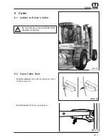
Page 57: ...iver s Cabin Do not climb up or down the ladder while the mower is moving 6 2 Open Cabin Door From the outside unlock with the ignition key press the button and open BMII 224 BMII 102 From the inside lift the door opening lever BMII 101 ...

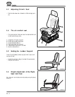
Page 58: ...ing the hand wheel 6 6 Height adjustment of the Right hand Arm Rest Move the arm rest into the desired position using the hand wheel 1 6 4 The air comfort seat The spring system of the seat can be adjusted from soft to hard using the lever B A adjustment of lumbar support B height and weight adjustment C longitudinal adjustment D higher adjustment of the seat E longitudinal adjustment of the seat ...

Page 59: ...wed to stay in the cabin during operation BMII 201 6 7 Drink Holder The drink holder is located on the right hand side next to the driver s seat Only insert suitable containers 6 8 Storage Compartment for the Operating Manual This storage compartment is loacted under the driver s seat Toopen Press button 1 ...

Page 60: ... and move it to the desired position The steering column will be locked when you release the pedal 1 Loosen unlocking lever 2 Set steering wheel to the position desired then re tighten unlocking lever 2 Only adjust the steering column when the machine has been shut down Adjust the sun blind according to requirements For driving on roads For road safety reasons the brake pedals must always be coupl...

Page 61: ... is located on the switch panel on the right hand side of the driver Push in cigarette lighter 1 it will pop out automati cally as soon as the spiral glows Danger of injury Only hold the hot cigarette lighter by the handle 6 16 Socket The socket is located on the switch panel on the right hand side of the driver The socket can be used for accessories Lift the flap 6 15 Diagnostics Socket CANinterf...

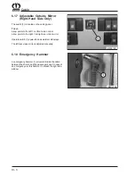
Page 62: ...t right rear vision mirror Operate switch 1 upwards downwards or sideways The left rear vision mirror is adjusted manually 6 18 Emergency Hammer An emergency hammer 1 is located inside the cabin between the driver s and the passenger s seat In case of an emergency use this hammer to smash the right side window 6 17 Adjustable Outside Mirror Right Hand Side Only ...

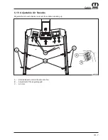
Page 63: ...n 6 19 Adjustable Air Nozzles A Knurled wheel to control the amount of air B Adjustment of the air guiding grid C Air slots Regulate the air nozzle blades to prevent the windows steaming up BMII 200 A B C C A B ...

Page 64: ...VI 8 Cabin ...

Page 65: ...80 7 1 Daily Checks Engine Fuel system Hydraulic system Indicator light test Radiatorsieve Lightfunctions Cooling system Brake Tyres Hydrostatic system BMII 208 1 7 4 Hydraulic Oil Level Lower all mowers and stop the engine The oil must be visible in the window 1 7 2 Soil Deposits in the Engine Bay The build up of dust oil and grass inside the engine bay is combustible and presents an increased fi...

Page 66: ...rol The engine coolant must always be visible in the inspection window For further information refer to the Maintenance Enginechapter Check the tyres daily for cuts or fractures and obviously low pressure Check the tyre pressure at least once per week with an accurateinstrument Vent fuel system For further information please refer to the operating instructions of Daimler Chrysler Engines enclosed ...

Page 67: ...VII 3 Check before Start up 7 9 Checks in the Cabin Indicator light test and light functioning see chapter Lights ...

Page 68: ...VII 4 Check before Start up ...

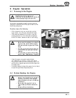
Page 69: ...ks Pay particular attention and be particularly aware until you have the required sense and ear for the engine and operatingnoises Avoid high loading or idling of the engine for more than 5 minutes during the first 20 operating hours BMII 182 1 2 3 8 Engine Operation 8 1 Running In the Engine The engine is immediately ready for normal operating conditions particular caution is required however in ...

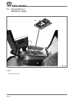
Page 70: ...VIII 2 Engine Operation 8 3 Prerequisites for Starting the Engine BMII 185 A Settings Drive release A to off ...

Page 71: ...before attempting to start again If the engine does not start within 20 secs wait at least 2 min before attempting to start again BMII 177 1 BMII 177 1 8 5 Switching On Ignition II The ignition is switched on The following indicator lights will illuminate Engine failure indicator light 2 for approx 2 seconds Job computer carries out internal system check The basic display appears Job computer carr...

Page 72: ...mes away from the battery Always connect the battery poles correctly the earth cable to the minus pole and the starter cable to the battery plus pole Not observing the correct polarity between the battery and alternator can cause serious damage to the electrical system Always connect the plus pole first and then the minus pole 8 9 Stopping the Engine Before finally switching off allow the engine 1...

Page 73: ...engine to run for approx 1 to 2 minutes before finally turning it off 8 11 In Cold Weather Fill the fuel tank completely at the end of each working day especially at the end of a working season to prevent condensationforming Always use a so called winter diesel fuel for operation in cold seasons at temperatures below 10 C 50 F See chapter Engine Coolant for mixing and use of the coolant ...

Page 74: ...VIII 6 Engine Operation ...

Page 75: ...entre stop immediately and rectify the fault If you cannot rectify the fault inform the customer service or your KRONE dealer Never drive with an engaged parking brake 9 2 Starting Engine See chapter 8 Engine Operation for more details The self propelled high performance mower conditioner swings out Be careful when driving around curves 9 3 Driving and Steering The steered wheels are at the rear o...

Page 76: ...Road Driving For road safety reasons the brake pedals must always be coupled by moving the locking lever No individual wheel brake available Before the start of every trip check the brake function 9 4 Brakes By operating the foot brake the hydrostat decelerates automatically The brake function must be checked before the start of every trip During road driving the engine speed is automotively contr...

Page 77: ...iving lever forwards will cause the machine tomoveforwardsandaccelerate If the lever is released it will return to its central position automatically The speed remains constant Movingthedrivingleverbackwardswilldeceleratethe machine It is decelerated until it comes to a standstill byadherence 9 7 Setting the Accelation Behaviour Using the switch 1 is possible even while driving to select fourdiffe...

Page 78: ...ground drive by selecting a lower shift step this will reduce the oil temperature Fast change of direction The Big M II decelerates to a standstill automatically lifts out all three mowers and accelerates in the opposite direction approx 70 of the previous driving speed while driving tap the driving lever to the left and simulta neously press the activation button on the rear side of thedrivinglev...

Page 79: ... to remain on the cabin platform Move the front mower to the central position when employing the levelling mechanism option The front mower is in central position as soon as the arrow 1 is adjusted central to the top link 2 SFM04290 2 1 1 2 2 1 BMII 209 1 BMII 220 To meet requirements for a sufficient spacing to electrical overhead lines the total height of the machine may not exceed 4 m 13 ft Whe...

Page 80: ...the danger area Never tow over long distances The spring is located at the spring storage cylinder below thefrontapron If the machine does not build up the oil pressure fir disen gaging the parking brake the parking brake can be disen gaged manually To do this the spring 1 must be set to Block Loosen nuts 2 Set spring 1 to Block Tighten nuts 2 fix by locknut ...

Page 81: ...liability for damage undertaken by the manufacturer null andvoid The mowers are suitable for and intended for cutting crops growing on the ground The mowers are not suitable for mowing embankments Maintain an adequate safety distance to the cutting tools during operation The support skids must rest on the ground before start up and during work Stones and similar objects can also be slung even when...

Page 82: ...on the mowers e g guards and guard plates protects against flying stones and similar objects as well as prevents dangerous parts being accessed SFM04290 2 1 3 3 1 2 10 2 Adjusting the Mowers Maintenance cleaning and repair work should be done only when the machine is at a standstill Switch off the engine remove the ignition key Secure the machine from rolling away After completing maintenance work...

Page 83: ...he drive is switched off and the tractor engine is at a stand still Remove the ignition key Secure the tractor against rolling away 10 2 3 Setting the Cutting Height Side mowers Disassemble the lynch pin 1 Remove the securing ring 2 Adjust the direction of adjustment ratchet 4 rotation on thelever 3 Lengthening the threaded spindle produces a smaller cutting height Shortening the threaded spindle ...

Page 84: ...3456789012345678901212345678901234 1234567890123456789012345678901212345678901234 1234567890123456789012345678901212345678901234 1234567890123456789012345678901212345678901234 1234567890123456789012345678901212345678901234 1234567890123456789012345678901212345678901234 123456 123456 123456Additional high cut skids have to be installed i t a c i d n I n o B z l a c i t e r o e h t g n i t t u c t h...

Page 85: ... any marks on the ground The adjustment of the compensation springs must only be carried out when the front disc mower is in transport position In working position the compensation springs are under a high tension Taking off the compensation springs when the mower is in working position can cause serious injury The lower screw in sections of the compensation springs must be completely screwed in F...

Page 86: ...rive shaft with the tools provided during the gear shift process SFM1 380 2 1 10 2 6 Setting the Conditioner Cover Plate on the Front Mower Two conditioner speeds can be set on the Schalt getriebe This influences the efficiency of the conditioner andpowerconsumption Normal operation 700 r p m Maximum operation 1000 r p m EC 0 031 10 2 5 Setting the Conditioner Speed Remove the wing screw 2 on the ...

Page 87: ...2 1 3 Always check the conditioner roller 1 for damaged V tines 2 beforeoperation Straighten bent tines Replace broken tines Check bearing pins and bushing on tine mountings To avoid losing tines replace bearing pins and bushings in goodtime The conditioner shaft turns at up to approx 1000 r p m Bent and broken tines cause unbalanced rotation For this reason replace broken V tines immediately 10 2...

Page 88: ...the swath width so that the track of the mower still remainsfree Loosen ring nut 1 Set swath width Tighten the ring nut 1 again BM300120 1 1 SFM03080 1 1 Setting the Roller Pressure Loosen the lock nut 1 spanner size 41 Turn the spindle on the screw head 2 spanner size 55 Turn clockwise greater application force Turn anticlockwise lower application force Tighten the lock nut 1 again Readjust the r...

Page 89: ... the transverse link 1 until the distance a between the side mower 4 and the extension arm 5 is set to 60 mm Tighten the lock nut 2 on the transverse link 1 BM201180 2 3 1 4 5 a BM201120 1 2 3 4 10 2 11 Front mower guiding plates There are guiding plates situated in front mowers 3 in the area of the swath former 2 These are fitted to the housing with fixture screws 1 If the swath is not deposited ...

Page 90: ...0 M 27x2 1150 1650 1950 M30 1450 2100 2450 Maintenance cleaning and repair work should be done only when the machine is at a complete standstill Shut down the engine and remove the ignition key After completing maintenance work reattach all protective plates and protective devices properly Avoid skin contact with oil and grease With injuries caused by oil escaping under pressure get the assistance...

Page 91: ...rd 2 back by hand and turn the protecting tubes against each other until the lubrication nipple 1 becomes visible All other lubrication nipples on the universal joint shafts must be lubricated according to the adjacent illustration SFM A 05 D A N G E R 2 1 SFM A 06 40h 8h 8h 20h 40h 8h 8h 10 3 4 Required Quantities and Lubricant Designations for Gearboxes 10 3 5 Oil level check and oil change inte...

Page 92: ...is also used to measure the oil level of the side mowers Oil change Unscrew dip stick 2 Unscrew oil draining screw 4 Collect the oil in a suitable vessel Fit oil draining screw with new seal Refill oil from the top dip stick hole Screw in dip stick 2 Oil quality see section 10 3 4 Oil capacity see section 10 3 4 Oilinspection Intervals see section 10 3 5 Remove check screw 1 Oil level up to bore h...

Page 93: ...ary top up oil SAE 90 fit check screw 10 3 8 Input gearbox Front mower The used oil must be correctly disposed of EC 0 041 Oil change Intervals see section 10 3 5 Unscrew the oil draining screw 2 Collect the used oil in a suitable collectionvessel Fit oil draining screw 2 Fill oil through hole 3 Oil level up to hole 1 Oil quality see section 10 3 4 Oil capacity see section 10 3 4 Oilinspection Int...

Page 94: ... the spirit level on the cutting disc hub parallel to the directionoftravel Oil level up to bore hole If necessary top up oil SAE 90 fit check screw Carrying out oil check Lower guards Nobody should be in the danger zone around the machine Switch off engine Remove ignition key Allow the machine to run briefly Wait until the cutterbar has come to a standstill Remove the oil check screw 1 on the cut...

Page 95: ... can continue to rotate after the drive has been switched off Only approach once the work tools have come to a complete standstill Only carry out work on the mower if the PTO shaft has been disengaged the engine turned off and the ignition key removed Secure the tractor against unintended start up and against rolling Safe operation is only guaranteed if the cutter blades have been fitted properly ...

Page 96: ...placement of the blades check the material thickness of the securing pins and the leaf springs Damage or worn securing pins have always to be replaced by sets on each mowing disc Replace the leaf springs if necessary EC 0 017 min 14 mm min 14 mm min 3 mm The material thickness of the retaining bolts must not be less than 14 mm at the weakest point The material thickness of the leaf spring must not...

Page 97: ...e retaining bolts must not be used more than 1 times After changing the blade check that they fit perfectly and check that they are freely moblile Push the special tool 1 blade key between the cutter disc 4 and leaf spring 3 and press down with onehand Guide blade 2 onto retaining bolt and allow the blade key to return upwards 10 4 4 Changing blades on cutter discs with quick release blades After ...

Page 98: ...n the areas marked 1 each should be approx 30mm Do not weld the edges 2 On the lower surface of the cutter bar weld the lining 3 along the whole length in area 5 with the cutter bar Do not weld the edges 4 Adjust the welding current and the welding material to the cutter bar materi al and to the lining or carry out a trial welding if necessary EC 0 010 EC 0 012 Open the seam of the old lining Disa...

Page 99: ...e lower belt pulley 5 and then pull out towards the top Reassembleinreverseorder Damaged drums or discs lead to un balanced rotation and thus to damage Replace immediately The tension spring for the belt should on the CV version have a measurement of 215 mm on the CRi version have a measurement of 290 mm A CRI 0 004 10 5 Conditioner Belt Drive Clean the cover casing 2 of the belt drive at regular ...

Page 100: ...X 20 Mowers 10 6 Front Mower Lubrication Chart EC 087 1 ...

Page 101: ...iter Zinken Aufbereiter Zinken Aufbereiter Rollen Aufbereiter Rollen Aufbereiter Rollen Aufbereiter SFM02140 15h SFM02140 15h SFM04030 50h 15h SFM04030 50h 15h SFM02070 30h 30h SFM02100 15h SFM02100 15h BM300150 SFM02170 50h BM300260 15h 50h BM300140 15h 15h 50h BM300260 15h 50h BM300140 15h 15h 50h ...

Page 102: ...olts 3 and 4 of the conditioner deflector plate 1 BMS01030 1 4 3 2 Releasing the clamping levers Release the clamping levers 1 and 2 located at the outer side of the mower 3 BMS01070 1 3 2 Maintenance cleaning and repair work should be done only when the machine is at a complete standstill Shut down the engine and remove the ignition key After completing maintenance work reattach all protective pl...

Page 103: ...e the inner clamping levers 1 and 2 of the mower 3 Check the V shaped tines 1 and the retaining bolts 2 of mowing unit 3 for damage Check the retaining bolts and the V shaped tines for damage Damaged or missing retaining bolts and knives have to be replaced immediately BMS01040 1 3 2 1 2 BMS01100 BMS01120 1 2 3 Removing the guard Undo the hex head bolts 1 Remove guard 2 and store it at a secure pl...

Page 104: ...Slowly lower the auger type cross conveyor 1 onto the mower 2 At the end of the lowering process be sure to introduce the auger type cross conveyor into the guide pins 1 and 2 The surfaces 3 and 4 must be level with each other at either side of the mower Locking the clamping levers Lock the clamping levers 1 and 2 located at the inner side of mower 3 Be sure the clamping levers 1 and 2 are under t...

Page 105: ...ler pulley 2 slowly and withdraw mounting lever 1 With V belt under tension dimension X must be equal to approx 5 mm Installing the guard Install guard 1 onto mower 3 using the hex head bolts 2 x BMS01312 4 2 1 3 BMS01340 1 2 3 Also lock the outer clamping levers 1 and 2 Be sure the clamping levers 1 and 2 are under tension when being locked Retighten as required BMS01290 1 2 ...

Page 106: ...wer 3 can be removed as follows Before removing the floor plates 1 and 2 be sure that the ignition key is removed and the machine is secured so that it cannot start to move on its own The following steps are described for the right hand mower side The removal of the floor plates located on the left hand mower side has to be carried out in an analogous way BM300190 1 2 BM301080 1 2 3 Lock the mowin...

Page 107: ...n in the figure 10 8 4 Engaging the auger montitoring mode To engage the auger monitoring mode you must first activate it as follows at the Infocenter Before switching on the ignition be sure no persons are standing in the immedia te vicinity of the machine BMII 157 F1 F2 F3 F4 1 BMII 162 F1 F2 F3 F4 Set ignition key to position I or II Wait for the self test to run After the ignition has been swi...

Page 108: ... 146 1 2 Conversion from cross feeding BSS to wide spreading mode When switching the Big M from cross feeding BSS to wide spreading mode remove the lubrication points 1 and 2 Do not close the removed lubrication lines ...

Page 109: ...a around the oil dip stick before pulling it out When checking the oil level must be between the lower and the upper mark of the oil dip stick After checking the oil level plug the oil dip stick back in again 11 1 Soil Deposits in the Engine Bay The build up of dust oil and grass inside the engine bay is combustible and presents an increased fire hazard Keep the engine and the engine bay clean at ...

Page 110: ...d sealing ring Screw in and tighten screw cap 4 with filter element Torque 25Nm Set three way cock 3 to pos I so that the return line is shut as in initial position Open shut off valve 1 at the preliminary fuel filter For further information please refer to the operating instructions for Daimler Chrysler Enfines supplied chapter Replacing the Fuel FIlter Insert After completing maintenance and rep...

Page 111: ...apacity approx 560 l BM300070 1 the operating instructions for Daimler Chrysler Engines supplied chapter Fuels the fuel regulation by Daimler Chrysler supplied Forfurtherinformationpleasereferto Stop engine when the machine is to be filled up The filler neck is closed by the tank cap The tank is vented by an orifice in the tank cap Before removing the tank cap clean its surrounding area from grass...

Page 112: ...ent fuel system BMII 178 F1 F2 F3 F4 1 the operating instructions for Daimler Chrysler Engines supplied chapter Venting the Fuel System For further information please refer to 11 8 Fuel Level With the ignition switched on check the fuel level using the fuelgauge 1 ...

Page 113: ...o provides corrosion and freezing protection up to 37 C Cooling system density additives may not be used BMII 182 1 2 3 11 11 Engine Coolant Control Never open the cap while the engine is hot Switch off the engine and wait until the engine has cooled down Required quantity 44 litres 11 10 Engine Coolant Engine Coolant Control Check engine coolant level daily The engine coolant level must be visibl...

Page 114: ...hen searching for leakages Protect hands and body If any fluid penetrates the skin it must be removed immediately by a doctor who is familiar with this kind of injury serious infections could otherwise result Doctors who are not familiar with this kind of injury should obtain the corresponding information from a competent medical source Regularly check hydraulic lines and replace if damaged or age...

Page 115: ...11 13 2 Main block 2 1 BMII 202 BMII 214 Y23 Y25 Y21 Y16 Y22 Y24 Y20 Y15 Y11 Y9 Y10 Y8 Y29 Y27 Y26 Y6 1 2 3 Y7 No Description 1 Suspension pressure control 2 Pressure control 3 Main valve pressure control Y6 Front axle selection Y7 Rear axle selection Y8 Front drive Y9 Right drive Y10 Left drive Y11 Parking brake Y15 List suspension Y16 Lower suspension Y20 Lift front Y21 Lower front Y22 Lift righ...

Page 116: ...g the laterals mowers into operating position ustable throttles 3 and 4 for the setting the speed of moving the lateral mowers into operating position are located on the main block on the left hand side in driving direction at the hydraulic cylinders for the drive Lowering speed of lateral mowers adjustable throttle 3 for setting the speed of moving the right hand side lateral mower into operating...

Page 117: ...lic Oil Medium CASTROL HYSPIN AWS 46 SHELL Fluid BD 46 Shell Tellus Öl 46 Shell Hydrol DO 46 COFRAN Cofraline extra 46 S Stuart Theunissen Hydrocor E 46 ISOCOR E46 Cofraline extra 46 S DEA Econa PG 46 Astron HLP 46 TOTAL Azolla ZS 46 ELF ELFOLNA 46 ELFOLNA DS 46 TRIBOL Tribol 772 Tribol ET 1140 46 Tribol 943 AW 46 ENGEN Engen TQH 20 46 VALVOLINE Ultrasyn PG 46 ESSO Hydrauliköl PGK 46 NUTO H 46 VER...

Page 118: ...Once the filter seal touches the sealing surface of the filter housing tighten the filter by 3 4 to 1 1 4 turns by hand Donotovertighten Check filter for leaks while the engine is running and tighten if necessary BMII 183 1 2 3 Lower all mowers and turn off engine Oil inspection Timeinterval every50h Oil must be visible in the inspection window 1 If necessary top up oil 2 Oil change Time intervals...

Page 119: ...Distribution Transmission Capacity 6 0 l Oil inspection Timeinterval beforeeveryuse Unscrew the oil check screw 2 Oil level up to bore hole If necessary top up oil synthetic DIN 51502 PGLP Fit check screw 2 Oil change Timeinterval every100operatinghours howeverat least once per year Unscrew the oil draining screw 3 Collect the used oil in a suitable collection vessel Fit oil draining screw 3 Fill ...

Page 120: ...iled information on fitting tyres on agricultural machinery can be obtained from the tyre manufacturers Never operate the self propelled high performance mower conditioner with the tyre pressure which is normal when the tyres are dispatched Keep the valve caps fitted on the valves to keep dirt out Check tyre pressure frequently 11 21 Wheel Fixing Tighten the wheel nuts after the first and then eve...

Page 121: ...er conditioneris equipped with two batteries each 12 V 135 AH which areconnectedparallel The battery will drain if the ignition is set to stage 1 or 2 even if the main switch is switched off 12 Maintenance Electrical System 12 1 Electrical System Specifications Alternatorpower 14V 150 A Numberofbatteries 2 Batteryvoltage 12 V Battery capacity 2x 135 AH 1 BMII 210 I II 2 BMII 231 During repair work...

Page 122: ... the marking above the plate upper edge Only use distilled water Always keep the battery clean of dust and chaff Batteries develop a highly explosive electrolyte gas Avoid ignition sources and naked flames near the battery Before carrying out work on the electrical system or on the engine always disconnect the earth cable or open the battery main switch Quick charging When quick charging the batte...

Page 123: ...ry poles correctly The plus cable coming from the starter to the plus poles the minus cable coming from earth to the minus poles Not observing the correct polarity between the batteries and alternators can cause serious damage to the electrical system 12 9 Alternator Before carrying out work on the electri cal system remove the earthing wire to prevent any damage For further information please ref...

Page 124: ...able connections clean and tighten cable connections on the starter Clean the earthing wires on the motor and tighten the connection to the motor Battery power too weak check electrolyte level as well as acid density recharge battery if necessary Flat battery Chargebattery Use of incorrect engine oil viscosity Always use the right engine oil according to the specifications Faulty starter safety re...

Page 125: ...0 A Earth GND LD4 Lower mower right LD22 Position mower left F12 10 A Voltage supply UV3 LD5 Lift mower right LD23 Free F13 25 A Voltage supply UV1 LD6 Push off left mower LD24 Axle suspension position LD7 Levelling system right LD25 Auger speed right LD8 Levelling system left LD26 Auger speed left LD9 Lift mower front LD27 8V digital LD10 Fan reversal LD28 8V analog LD11 Lift mower left LD29 5V s...

Page 126: ...6 F138 F123 F101 F102 F124 F135 F137 F134 F140 F139 F144 F143 F142 F141 F146 F130 F133 F132 F131 F128 F127 F145 F126 F125 F129 F108 F107 F106 LD119 LD120 LD109 LD108 LD122 LD110 LD124 LD105 LD101 LD107 LD106 LD103 LD104 LD121 LD116 LD115 LD114 LD113 LD111 LD112 LD117 F114 LD123 LD102 LD118 Big M II Kabine Big M II cabin ...

Page 127: ... 115 15A Cabin roof centre left F 138 10A Ignition stage 2 MR F 116 15A Cabin roof lateral left F 139 15A n b F 117 15A Cabin roof lateral right F 140 15A DIN Socket F 118 15A Worklight side F 141 15A Cigarette lighter F 119 15A Worklight rear F 142 15A Console F 120 15A cabin bottom left F 143 15A n b F 121 15A cabin bottom right F 144 15A n b F 122 15A cabin bottom side F 145 5A Parking brake F ...

Page 128: ...Unterverteiler 1 Fuses Value Funktion Fuses Value Function F1 15A Supply Voltage V1 F16 7 5A n b F2 15A Supply Voltage V2 F17 7 5A Axle disengagement F3 15A n b F18 7 5A Reversing horn F4 15A n b F19 7 5A Brake light F5 10A n b F20 15A Lift axle suspension F6 10A n b F21 15A Lower axle suspension F8 10A n b F22 15A Free F9 10A 12V Socket F23 7 5A n b F12 7 5A n b F24 7 5A n b F13 7 5A 12V Elektron...

Page 129: ...D21 Free LD4 Supply voltage V1 LD22 Free LD5 Supply voltageV2 LD23 Free LD6 Load F3 LD24 Street field LD7 Load F4 LD25 Free LD8 1 2 rear suctin volume LD26 Automotive drive LD9 1 2 front suction volume LD27 Free LD10 Load F16 LD28 Free LD11 Axle disengagement LD29 Safety output KMC1 LD12 Reversing horn LD30 Door switch LD13 Brake light LD31 Seat switch LD14 Lift axle suspension LD15 Lower axle sus...

Page 130: ... den Unterverteiler 2 Fuses Value Function Fuses Value Function F1 15A Supply Voltage V1 F16 7 5A n b F2 15A Supply Voltage V2 F17 7 5A n b F3 15A Supply Voltage V3 F18 7 5A n b F4 15A Supply Voltage V4 F19 7 5A n b F5 10A RMC Teleservice F20 15A Fan reversal F6 10A n b F21 15A 12V Teleservice F8 10A Central lubrication F22 15A n b F9 10A 12V Socket F23 7 5A Release electronics supply F12 7 5A n b...

Page 131: ...r LD3 Ignition stage 1 relay K3 LD21 Free LD4 Supply VoltageV1 LD22 Free LD5 Supply VoltageV2 LD23 Free LD6 Supply VoltageV3 LD24 Street Field LD7 Supply VoltageV4 LD25 Free LD8 Load F14 LD26 Automotive drive LD9 Load F15 LD27 Free LD10 Load F16 LD28 Free LD11 Load F17 LD29 Free LD12 Load F18 LD30 Door switch LD13 Load F19 LD31 Seat switch LD14 Fan reversal LD15 Load F21 LD16 Load F22 LD17 Load F2...

Page 132: ...Check oil level and replace if necessary 108 Engine failure Turn off engine immediately Eliminate failure 109 Cooling water temperature Check Cooling water level and refill if necessary Check coolant circuit 110 Suction return line Check wiring Replace sensor 111 Tank sensor Check wiring Check protective resistor Replace tand sensor 112 Tank level Refill fuel 113 Drive release switch Operate switc...

Page 133: ...ght auger drive If no auger drive is present deactivate auger monitoring Check driving belt Check sensor 121 Slip of left auger drive If no auger drive is present deactivate auger monitoring Check driving belt Check sensor 122 123 KKC restart Check KKC power supply Check wiring ...

Page 134: ...Digital Pot Error Digital Pot error 20 EV DAC Error EV DAC error 21 I2C Bus Error I2C Bus error 30 Error on control loop pump 1 Pump 1 control loop error X 31 Error on control loop pump 2 Pump 2 control loop error X 32 Feedback error pump 1 Pump 1 pivoting angle sensor error Signal out of range Check wiring Check signal Replace or adjust pivoting angle sensor X 33 Feedback error pump 2 Pump 2 pivo...

Page 135: ...he parking brake Parking brake switch not in normal position Check parking brake switch and wiring Check sensor and wiring Replace sensor X 43 Feeding pressure too high Check wiring Replace sensor 44 Oil temperature too high Let machine cool down Check wiring Replace sensor X 45 An attempt was made to drive without drive release Drive release switch is not switched on Check drive release switch an...

Page 136: ...XII 16 Maintenance Electrical System ...

Page 137: ... done only when the machine is at a complete standstill Shut down the engine and remove the ignition key Repair maintenance service and cleaning must only be carried out by authorised special ists When carrying out repair maintenance service and cleaning of the coolant circuit coolant emissions can occur both liquid or gaseous which pose a hazard for man and environ ment Take suitable protective m...

Page 138: ...sure 40 60bar Density liquid at 25 C 1206 kg m3 Inflammabitity limits in air noninflammable Environmental data CFC134a ODP Ozonolyispotential ODP 0 CLP Chlorbelastungspotential CLP 0 HGWP Greenhouseeffect HGWP 0 26 PCR Photochemicalreactivity PCR 0 5 Technical Data Component Performance data Evaporator Cooling capacity 5 200 Watt Heater Heating capacity 4 000 Watt Fan 1000 m3 h freiblasend Voltage...

Page 139: ...XIII 3 Maintenance Air Conditioning and Heating 13 5 Air Intake and Distribution BMII 217 BMII 216 ...

Page 140: ...soiling located outside the cabin For cleaning replacing or assessing the degree of soiling the slotted grill must be removed Open the locking device using a square wrench by turning clockwise by 90 After opening the slotted grill can be folded to the left The wedge filter cell is then freely accessible and can be taken out of the fan Before the start of each ride the filter should be checked for ...

Page 141: ...ust be above the set thermostat temperature usually 1 C for the compressor to switch on Sinceanoperatingover pressureispresentinsidethecoolant collector it manufacturing and testing is subject to the Druckbehälterverordnung pressurevesselcode In this code the pressure vessels are classified according to thepermissibleoperatingover pressurepinbar itscapacity inlitersandthepressurecapacityproductpxl...

Page 142: ...1 Check the condenser component in front of the cooler forsoiling Clean the condensor block depending on its degree of soiling however at least once per month Blow through the condenser block with compressed air from the inside to the outside making sure that the fins are not damaged ...

Page 143: ... bearings or electrical electronic parts Lubricate the self propelled mower according to the lubrication chart Grease the threads of adjusting screws and similar parts relieve springs Transport locking catch for lateral mowers Grease the bolt Grease the blank piston rods of all hydraulic cylinders and retract as far as possible Wet all lever joints cutterbar and bearing points without lubrication ...

Page 144: ...t tension Removecoversfromengineopenings Lubricate the machine completely according to the lubricationchart Check whether all pins have been tightened and all split pins are fitted Check all seals as well as the quantities in the cooling system The frost and corrosion protection agent must also be used in the cooling system during the summer months as it protects the system against corrosion Check...

Page 145: ...the belt pulleys 4 if necessary using screws Apply new V belts Tighten the tension pulley spring to a 200 Make sure the fan blade is in a central position in the radiator cover 15 2 Deployments arms When the deployment arm is on the right the loaded length of spring should be a 95 mm When it is on the left the loaded length of spring should be a 95 mm SFM1 450 a SFM1 460 a SFM1 510 4 1 5 a 2 3 ...

Page 146: ...side Loosen the lubrication wire 2 Exchange the belt 4 and test that they are in the correct position Stretch spring 1 to a length of 90 mm Mount the cover 3 on the right hand side Mount the belt covers 15 3 Mower drive Belt tension is generated using the hydraulic cylinder pressure50bar Reset the single action cylinder using the springs BMII 218 BM201050 1 3 4 2 ...

Page 147: ...M202340 1 1 1 2 2 2 1 Drive belt side mowers Remove the fixture screws 1 of the belt covers 2 on both sides Removethebeltcovers 2 Replace the belt and check that it is in the correct position Reattach the belt covers 2 ...

Page 148: ...XV 4 Belt Drive ...

Page 149: ...e steering cylinder armature on the rear axle Tighten the mounting bolts on the steering cylinder armature on the wheel hubs Tighten the mounting bolts on the track rod 16 2 Every 10 Operating Hours Engine check oil level Hydraulic system check oil level Tyres If you have to top up the engine oil during the running in time the oil viscosity should be choosen according to the seasonal requirements ...

Page 150: ...ixture top up antifreeze mixture if necessary Check foot brake setting Adjust parking brake Bowden cable if necessary Check that turbo charger screw connections and hose connections are fitted properly Clean the paper filter elements in the cab Check the oil level in the central gearbox Check the oil level on the cutterbar 16 4 Every 250 Operating Hours Includes all work described under Every10Ope...

Page 151: ...entral gearbox oil 16 6 Every 1500 Operating Hours Replace dry air filter element and air filter safety element 16 7 Whenever Necessary Replace both air filter elements Change cab air filter Cleanpre filter Change hydraulic oil filter Changefuelfilter Cleanbatteries 16 8 Every Year Havestarterchecked Havealternatorchecked Check hose connections on the air intake system Check the air conditioning 1...

Page 152: ...aintenance 16 10 Basic Machine Lubrication Chart BMII 232 SFM03280 30h SFM03320 30h SFM03270 50h 50h SFM03290 30h SFM03260 50h SFM03240 30h SFM03250 30h SFM1 010 SFM1 020 Pendellager Achse Lagerung Seitenausleger Gelenkwellenlager 30h 30h ...

Page 153: ...must be fitted to the front mower and to the lateral mowers BMII 247 A 1 1 Installing the guard cloths Fit guard cloths 1 to mowing unit 5 using the enclosed strips 2 washers 3 and bolts 4 The hem of the guard cloths should always face the inside BM300180 1 2 3 4 5 1 Lateral guard cloths 2 Front guard cloths 3 Mowingunit ...

Page 154: ...A 2 Appendix ...

Page 155: ...A 3 Appendix ...

Page 156: ...ernard Krone GmbH Heinrich Krone Straße 10 D 48480 Spelle Postfach 11 63 D 48478 Spelle Phone 049 0 59 77 935 0 Fax 049 0 59 77 935 339 Internet http www krone de eMail info ldm krone de konsequent kompetent 7 Mai 2002 ...

Reviews: