X - 5
Mowers
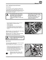
Side mowers
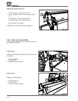
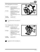
The side mowers are relieved via four extension springs (1)
on the left-hand and right-hand arm.
The ground pressure can be set by moving the pin (2).
Raise the side mowers above the stand-by position
so the compensation springs are relieved.
First remove the lynch-pin and then pull out the pin (2).
Pin further to the left: lower ground pressure
Pin further to the right: higher ground pressure
Insert pin (2) and secure with lynch-pin
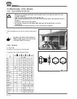
Maximum relief when driving on the
road. Mount bolts in stage 3 (medium
bore).
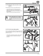
10.2.4 Setting the Ground Pressure
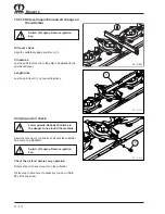
The ground pressure of the cutterbars is adapted to the
local conditions using compensation springs. In order to
protect the turf the cutterbars should be relieved to such an
extent that they do not jump during mowing and do not
leave any marks on the ground.
The adjustment of the compensation
springs must only be carried out when
the front disc mower is in transport
position. In working position, the
compensation springs are under a high
tension.
Taking off the compensation springs
when the mower is in working position
can cause serious injury.
The lower screw-in sections of the
compensation springs must be
completely screwed in.
Front mower
BMII-189
1
2
3
4
6
5
SFM05230
1
2
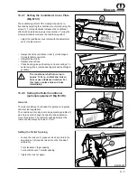
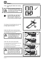
Before adjusting the adjustment piece (1) the front
mower must be set to transport position.
Undo lynch-pin (3).
Unhook springs (2).
Insert adjustment piece (1) into the hole desired.
Hang springs (2) and secure with lynch-pin (3).
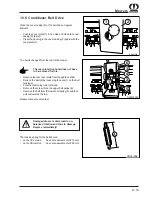
On the mower side the springs are mounted in the top
hole (6).
Adjustment piece (1) in top position (4) = lower spring
tension = increased ground pressure
Adjustment piece (1) in bottom position (5) = higher
spring tension = reduced ground pressure
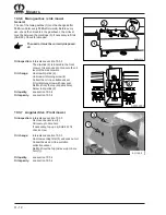
For slope compensation the front mower
must be in central position (see chapter
3.4, Multi-function Lever)
Summary of Contents for Big M II
Page 2: ......
Page 4: ...Vorwort Notizen ...
Page 28: ...II 14 Safety ...
Page 35: ...III 7 Controls 3 7 Roof Console BMII 192 A B A Compartment B Airconditioning heating ...
Page 42: ...III 14 Controls ...
Page 64: ...VI 8 Cabin ...
Page 68: ...VII 4 Check before Start up ...
Page 74: ...VIII 6 Engine Operation ...
Page 100: ...X 20 Mowers 10 6 Front Mower Lubrication Chart EC 087 1 ...
Page 136: ...XII 16 Maintenance Electrical System ...
Page 148: ...XV 4 Belt Drive ...
Page 154: ...A 2 Appendix ...
Page 155: ...A 3 Appendix ...

