background image

Maintenance

73

Pos : 25.23. 1 /Ü berschrif ten/Ü berschrif ten 2/F-J/H auptgetriebe @ 0\ mod_1197005740033_78. doc @ 15416

10.6

Main gearbox

Pos : 25.23. 2 / BA/ Wart ung/Öl kontrolle_Wechsel/M ähwer ke/ Bild H auptgetriebe EC 7540/9140 @ 11\ mod_1223468187241_78. doc @ 147078

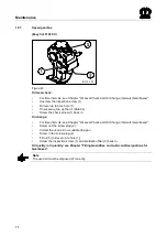
Fig. 39

Pos : 25.23. 3 / BA/ Wart ung/Öl kontrolle_Wechsel/ Öl kontr olle SAE 90 @ 0\ mod_1197008973815_78. doc @ 15649

Oil level check:

For time intervals, see Chapter "Oil Level Check and Oil Change Intervals (Gearboxes)".

Unscrew the inspection screw (1)

Oil level up to bore hole (1)

If necessary, top up the oil (SAE 90)

Screw the check screw (1) back in.

Pos : 25.23. 4 / BA/ Wart ung/Öl kontrolle_Wechsel/ Öl wechs el Versi on3 @ 1\ mod_1201255900073_78. doc @ 52826

Oil change:

For time intervals, see Chapter "Oil Level Check and Oil Change Intervals (Gearboxes)".

Screw out the oil drain plug (2)

Collect the used oil in a suitable drip pan

Screw in the oil drain plug (2)

Top up the oil (3) (oil level up to hole (1))

Screw the inspection screw (1) and locking screw (3) back in.

Pos : 25.23. 5 / BA/ Wart ung/Öl kontrolle_Wechsel/ Ölqualität / Ölmenge: siehe Kapitel @ 0\ mod_1197007859486_78. doc @ 15531

Oil quality / oil quantity: see Chapter "Filling Quantities and Lubricant Designations for
Gearboxes"

Pos : 25.23. 6 / BA/ Wart ung/Öl kontrolle_Wechsel/ Alt öl ordnungsgemäß ent sorgen @ 0\ mod_1197008117002_78. doc @ 15550

Note

The used oil must be disposed of correctly

Pos : 25.24 / BA/-----Seit enumbruc h------ @ 0\ mod_1196175311226_0. doc @ 4165

Summary of Contents for EasyCut 10000 Shift

Page 1: ... v EasyCut 7540 v v T Typ2 v EasyCut 9140 Shift v v T Typ3 v EasyCut 9140 CV v v T Typ4 v EasyCut 9140 CV Collect v v T Typ5 v EasyCut 10000 Shift v v T Typ6 v v v T abMasch Nr v from serial no v 819 340 v T Bestell Nr v Order no v 150 000 005 04 en v B Titelbild v v 29 06 2011 ...

Page 2: ...ective 2006 42 EC Machinery The signing Managing Director is authorised to compile the technical documents Spelle 01 12 10 Dr Ing Josef Horstmann Managing Director Design and Development Year of manufacture Machine No Pos 2 BA Vor wort Sehr geehrter Kunde 0 mod_1195626300326_78 doc 905 Dear customer Dear customer You have now received the operating instructions for the KRONE product which you have...

Page 3: ...ety Instructions 13 4 2 3 Safety conscious work practices 13 4 3 Safety Instructions and Accident Prevention Regulations 14 4 4 Attached devices 15 4 5 PTO operation 16 4 6 Hydraulic system 17 4 7 Tyres 17 4 8 Maintenance 18 4 9 Unauthorised Conversion Modification and Spare Parts Production 19 4 10 Inadmissible Modes of Operation 19 4 11 Working in the vicinity of power transmission lines 19 4 12...

Page 4: ...n 44 8 1 Function of the switches on the control unit 45 8 2 From transport into working position 46 8 3 Before mowing 47 8 3 1 Folding down the Safety Device 48 8 4 Swivelling parking support into transport position 49 8 4 1 Adjusting the lateral suspension arm 50 8 5 Headland Position 51 8 6 Detaching the machine 53 8 7 Parking 54 9 Settings 55 9 1 Adjusting the cutting height 55 9 2 Adjust over...

Page 5: ...level 76 10 10 Checking the Cutter Blades and Blade Holder 78 10 10 1 Cutter Blades 78 10 10 2 Blade screw connection 79 10 10 3 Blade Quick Fit Device 80 10 10 4 Periodical Inspection of the Leaf Springs 81 10 10 5 Periodical Inspection of the Cutting Discs Blade Drums 82 10 10 6 Abrasion Limit 83 10 11 Blade Changing on Cutting Discs 84 10 11 1 Blade Screw Connection 85 10 11 2 Blade Quick Fit D...

Page 6: ...veyor belts 107 14 7 3 Speed control of transport belts 108 14 8 Setting Conveyor Belt 109 14 9 Bar on cross conveyor is bent 109 14 10 Hydraulic system 110 14 10 1 Filling Quantities and Lubricant Designations 110 14 10 2 Oil Tank 111 14 10 3 Checking the oil level 112 14 10 4 Oil change 112 14 10 5 Replacing the hydraulic oil filter 113 15 Appendix 114 15 1 Hydraulic System Circuit Diagrams 114 ...

Page 7: ...Cut 3 mod_1204546850246_78 doc 70549 Note In the operating instructions which follow the disc mower will also be referred to as the machine Pos 7 4 BA Vor wort Beachten Sie für Maschi ne 0 mod_1195626904076_78 doc 944 Please note The operating instructions are part of your machine Only operate this machine after you have been trained to do so and according to these instructions It is essential to ...

Page 8: ...er wendungszweck 1 mod_1201707246738_78 doc 54055 3 1 Purpose of Use Pos 9 4 BA Ei nleitung EasyC ut Verwendungszweck Mäher 3 mod_1204547495418_78 doc 70590 The EasyCut disc mower is used for cutting crops growing on the ground except maize Pos 9 5 BA Ei nleitung Gültigkeit EasyC ut EasyC ut 7540 9140 10000 53 mod_1290076123328_78 doc 508702 3 2 Validity These operating instructions apply to disc ...

Page 9: ...ach No Type Note The entire identification plate represents a legal document and should not be altered or rendered illegible When asking questions concerning the machine or ordering spare parts be sure to provide type designation machine number and the year of manufacture of the relevant machine To ensure that these data are always available we recommend that you enter them in the fields above Not...

Page 10: ...consequential damage Pos 9 14 BA Einl eitung Technische D aten 0 mod_1195566374865_78 doc 594 3 6 Technical data All information illustrations and technical data in these operating instructions correspond to the latest state at the time of publication We reserve the right to make design changes at any time and without notification of reasons Pos 9 15 Abkürzungen Abkürzungen sprachneutr al EasyC ut...

Page 11: ...729 wa Type Easy Cut 10000 Shift Working width mm 9300 9600 Transport width mm 3000 Number of mowing discs 12 Number of mower drums 4 Conditioner system Speed of the conditioner rpm Width of conditioner system rpm Acreage ha h 10 0 11 0 Power consumption kW HP 110 150 PTO speed rpm 1000 Hydraulic connections required 2 x single action Service weight kg approx 1960 EW Single action control unit Pos...

Page 12: ...ion of the hazard warnings Danger DANGER Type and source of the hazard Effect Danger to life or serious injuries Measures for hazard prevention Warning WARNING Type and source of the hazard Effect Injuries serious material damage Measures for hazard prevention Caution CAUTION Type and source of the hazard Effect Property damage Measures for risk prevention Pos 11 4 BA Sicher heit Allgemeine Funkti...

Page 13: ... the safety instructions are not respected this could result in the forfeiture of any claims for damages Failure to follow the safety instructions could result for example in the following hazards Endangering of persons due to not protected working areas Breakdown of important machine functions Failure of prescribed methods for repair and maintenance Endangering of persons due to mechanical and ch...

Page 14: ...1 Use extreme caution when attaching or detaching implements onto or from the tractor 12 Always attach ballast weights properly to the fixing points provided 13 Observe permitted axle loads gross weight and transport dimensions 14 Check and attach transport equipment such as lighting warning devices and protective equipment 15 Actuating mechanisms cables chains linkages etc for remote controlled d...

Page 15: ... when attaching or detaching implements onto or from the tractor 2 Couple the respective application devices to the appropriate couplings e g three point suspension only and secure them in a way transport use that excludes inadvertent lifting or lowering of the device 3 When using three point linkage the attachment categories of the tractor and the device e g PTO speed hydraulic system must be coo...

Page 16: ... shaft make sure that no person is in the danger zone of the device 10 Never switch on the PTO if the engine is switched off 11 No one should be in the vicinity of the rotating PTO or PTO shaft when the PTO is in use 12 Always switch off the PTO shaft when the angle is too large or the PTO shaft is not required 13 Caution After disengaging the PTO danger due to the flywheel running on Keep away fr...

Page 17: ...the hydraulic system depressurise the system and switch off the engine Pos 11 6 12 BA Sicherheit H ydrauli kanl age Zusatz Alterung der H ydr auli kschlauchlei tungen 3 mod_1204552944856_78 doc 70772 8 Check the hydraulic hose lines at regular intervals and replace them if damaged or worn The new hoses must fulfill the technical requirements set by the manufacturer of the implement Pos 11 6 13 Ü b...

Page 18: ... edges use suitable tools and gloves 5 Oils greases and filters must be disposed of correctly 6 Always disconnect the power supply before working on the electrical system 7 If protective devices and guards are subject to wear check them regularly and replace them in good time 8 When performing electrical welding work on the vehicle and mounted devices turn the power supply off at main battery swit...

Page 19: ...d use of the operating instructions The limit values listed in the data charts should not be exceeded under any circumstances Pos 11 7 BA Sicher heit Ar beiten i m Ber eich von H ochspannungsleitungen 11 mod_1223357468516_78 doc 145505 4 11 Working in the vicinity of power transmission lines 1 Always take great care when working under or in the vicinity of power transmission lines 2 Ensure that wh...

Page 20: ...diately replace damaged or illegible adhesive labels Following repair work always attach appropriate adhesive safety stickers to all the replaced modified or repaired components Never clean areas carrying an adhesive safety label using a high pressure cleaner Familiarise yourself with the statement of the warning pictograms The adjacent text and the selected location on the machine provide informa...

Page 21: ... parts of the machine Wait until they have come to a complete stop b Move the protective devices into position prior to start up c When the machine is running keep your distance a b c Order No 939 576 0 Easy Cut 7540 2x EasyCut 9140 2x EasyCut 9140 CV 4x 4 When the machine is running keep your distance Order No 942 197 1 4x EasyCut 9140 CV only 5 While parts are moving never reach into areas where...

Page 22: ...ral EasyC ut EasyCut 10000 Shift 41 mod_1271851241507_0 doc 373499 EasyCut 10000 Shift Pos 11 16 BA Sicherheit Aufkleber EasyC ut Sicher hei tsaufkl eber EasyC ut 10000 Shift 42 mod_1272548214052_78 doc 379225 EC 321 0 5 5 3 3 5 5 3 3 5 3 5 6 2 1 5 3 5 Fig 3 ...

Page 23: ...od of time before being switched off completely Do not touch any moving parts of the machine Wait until they have come to a complete stop b Move the protective devices into protective position prior to start up c When the machine is running keep your distance a b c Order no 939 576 0 6x 5 While parts are moving never reach into areas where there is a risk of being crushed Order no 942 196 1 8x 6 K...

Page 24: ...ut 9140 Pos 11 20 BA Sicherheit Aufkleber EasyC ut Hinweisaufkl eber EasyC ut 7540 9140 30 mod_1251706235091_78 doc 294865 4 4 3 3 EC800020_4 1 1 6 6 7 7 2 2 5 5 2 2 9 9 8 8 Fig 4 1 27 000 241 0 2x 850 mm EasyCut 9140 CV 2 942 341 0 2x 893 mm EasyCut 9140 CV only 942 320 0 2x 600 mm EasyCut 9140 CV only 942 295 0 2x EasyCut 7540 EasyCut 9140 3 Order No 255 498 1 1x with blade screw connection 255 ...

Page 25: ...objet d une purge lors de la premi ère mise en route et une fois par an avant le d ébut de la saison The friction clutch must be bled at the first operation and once a year before the harvesting season La frizione di sicurezza deve essere sottomessa ad uno spurgo alla prima messa in campo come pure Vor der Erstinbetriebnahme und 1x j ährlich vor der Ernte muss die Reibkupplung gel üftet werden 939...

Page 26: ...e de seguridad debe someterse a una purga antes de la primera puesta en marcha y una vez al año antes de iniciarse la campa ña de trabajo E La s écurité à friction doit faire l objet d une purge lors de la premi ère mise en route et une fois par an avant le d ébut de la saison The friction clutch must be bled at the first operation and once a year before the harvesting season La frizione di sicure...

Page 27: ... be ordered directly from the manufacturer or from an authorized dealer see Section Contact 4 14 2 Affixing the Adhesive Safety and Information Labels Note Affixing an adhesive label Effect Adhesion of the label The surface for affixing the adhesive label must be clean and free of dirt oil and grease Pos 12 BA Sei tenumbruch 0 mod_1196175311226_0 doc 4165 ...

Page 28: ...re the machine against the possibility of rolling back Pos 13 6 BA Sicher heit Gefahr enhinweise Fehl erhafter Zusammenbau 1 mod_1202224212591_78 doc 58171 Danger Incorrect assembly Effect Danger to life serious injuries or serious damage to the machine Only authorised service centres may assemble the machine The machine must be assembled with special care Always heed the applicable accident preve...

Page 29: ...at II Kat III Kat III EC800030 Fig 6 Pos 13 12 BA Erstinbetriebnahme EasyC ut Kuppel punkte Text EC 7540 9140 11 mod_1223380216501_78 doc 145731 The three point coupling for the Easy Cut 7540 is only designed for Cat II The three point coupling for the Easy Cut 9140 and Easy Cut 9140 CV is designed for Cat II and Cat III Pos 13 13 BA Erstinbetriebnahme EasyC ut Kuppel punkte Text EC 10000 Shift 41...

Page 30: ...machine must be properly connected to the tractor Bring machine into transport position with tractor rear hydraulics P T O shaft drive and tractor engine OFF Activate tractor parking brake Remove the ignition key Pull the locking bolt 1 and bring into position III right hand and left hand side Make sure by visual contact that the locking bolt 1 is located in the centre of the oblong hole pos III I...

Page 31: ... work the lower suspension arms on the tractor must be secured by limiting chains or bars If the lower suspension arms 1 are equipped with catch hooks the following items must be taken into consideration High forces develop in the lower suspension arm bolts 3 especially in the headland position For this reason the catch hooks must be in a flawless condition Additionally the catch hooks must be sec...

Page 32: ...ctions refer to the operating instructions of the PTO shaft manufacturer Pos 13 27 BA Sicherheit Gel enkwell e Achtung Schwenkbereich Fr eiraum überpr üfen 9 mod_1220536308930_78 doc 126898 Caution Swivel range of the PTO shaft Effect Damage to the tractor or the machine Check the swivel range and clearance of the PTO shaft Pos 13 28 BA Erstinbetriebnahme Gelenkwelle Tr aktor wechsel Gel enkwellen...

Page 33: ... left hand hook For this reason the catch hooks must be in a flawless condition Additionally the catch hooks must be secured in the provided locking hole 4 against unwanted opening after the machine has been connected to the tractor Pos 15 4 BA Sicher heit Gefahr enhinweise M ähwer ke Achsl asten Beeinträchtigung der Lenkfähigkeit 9 mod_1220866555985_78 doc 128119 Warning Impairment of the steerab...

Page 34: ...99777037794_78 doc 34244 6 2 2 Connecting the hydraulic lines Pos 15 12 BA Sicherheit H ydrauli k Ver tauschen der H ydraulikkl eitungen 9 mod_1220871857985_78 doc 128182 Warning If the hydraulic hoses are interchanged when connecting them to the hydraulic system of the tractor the functions will be interchanged as well Effect Injuries serious damage to the machine Identify the hydraulic connectio...

Page 35: ...i ppschalter an der Bedienung EC 7540 9140 11 mod_1223382973595_78 doc 145841 The following functions of control devices depend on the setting of the flip switches on the control unit see chapter on Operation Function of the switches on the control unit Pos 15 20 BA Inbetri ebnahme EasyCut H ydrauli k Anschl uss H ydrauli klei tung EC 7540 9140 mit QFB 11 mod_1223382307470_78 doc 145819 Single act...

Page 36: ...by means of the power supply cable Insert the plug of the power supply cable into the tractor s continuous power socket Position the cable so that it will not come in contact with the wheels Pos 15 24 BA Sicherheit elektrische Bedi enung Achtung Anschluss der Bedienung 11 mod_1222421029499_78 doc 141746 Caution Connecting the electrical controls Effect Damage to the control unit Before inserting t...

Page 37: ...nsing Regulations the machine is equipped as follows by default 3 chamber rear lamps 3 direction indicator reversing light and brake light with red reflectors on the rear 4 with lateral yellow reflectors on the rear 5 Pos 15 30 BA Inbetri ebnahme EasyCut Bel euchtung Anschluss Bel euchtung T2 Bild EC 7540 9140 11 mod_1223384996095_78 doc 145948 2 5 3 4 EC810022 Fig 12 Pos 15 31 BA Inbetri ebnahme ...

Page 38: ...properly Never use a PTO shaft the protective devices of which have not been attached Replace damaged protective devices immediately Attach the safety chain of the PTO shaft so that the guard tube does not rotate simultaneously with the PTO shaft Pos 15 37 BA Sicherheit Gel enkwell e Falsche Zapfwellendr ehzahl 1000 U mi n 10 mod_1221819449336_78 doc 138326 Danger Incorrect PTO speed Effect Danger...

Page 39: ... Pos 15 44 BA Inbetri ebnahme EasyCut Anbau Gel enkwell e Zwischengel enkwell e Zwischeng elenkwell en Bil d EC 7540 9140 129 mod_1346747746275_78 doc 1154079 1 Fig 14 Pos 15 45 BA Inbetri ebnahme EasyCut Anbau Gel enkwell e Zwischengel enkwell e Zwischeng elenkwell e Text EC 7540 9140 129 mod_1346747092747_78 doc 1153895 1 The intermediate PTO shafts 1 for the tedder drives are coupled to the gea...

Page 40: ...mod_1223444129381_78 doc 146330 EC800009 1 4 1 2 2 3 2 Fig 15 Pos 15 50 BA Bedienung EasyC ut Abstellstütze Abstellstützen in Transportstell ung schwenken 12 mod_1224048566368_78 doc 149887 After the machine is attached swivel the parking supports into transport position Use the three point hydraulic system to raise the machine somewhat Swivel the parking supports 1 2 into transport position and l...

Page 41: ... devices switching the electrical control unit could cause functions to be triggered Caution is therefore advised during operation if there is anyone in the area of the machine To prevent functions from being triggered accidentally it is essential to turn off the control unit when the machine is being transported To move the entire machine to the transport position the cross conveyor belts must pr...

Page 42: ...rol unit Move the flip switch 3 to the Middle position see chapter on operation Function of switches on the control unit Activate the single action control device 1 red 1 to raise the mowing units slowly from the working position to the headland position Move the flip switch 2 to the Up position see chapter on operation Function of switches on the control unit Activate the single action control de...

Page 43: ...r swivelling the mowing units up that the right and left locks are engaged Pos 17 13 BA Fahr en und Transport EasyC ut Vergewissern dass di e Verrieg elungen ei nger astet sind Bild 11 mod_1223389421876_78 doc 146125 Fig 17 Pos 17 14 BA Fahr en und Transport EasyC ut Vergewissern dass di e Verrieg elungen ei nger astet sind 11 mod_1223388604657_78 doc 146104 By folding up the mowing units attached...

Page 44: ...the position of the control devices switching the electrical control unit could cause functions to be triggered Caution is therefore advised during operation if there is anyone in the area of the machine To prevent functions from being triggered accidentally it is essential to turn off the control unit when the machine is being transported To move the entire machine to the transport position the c...

Page 45: ...t position to the headland position and vice versa Bottom lower rocker switch 3 is activated 3 Rocker switch only active if rocker switch 2 is pointing down Left Control unit 1 red 1 raises or lowers the left mowing unit from the working position to the headland position or vice versa Control unit 2 red 2 raises or lowers the right mowing unit from the working position to the headland position or ...

Page 46: ...oc 146308 1 4 2 3 EC800038 Fig 19 Pos 19 10 BA Bedienung EasyC ut Tr ansport i n Ar beitsstellung mit Absperrhahn Text EC 7540 9140 11 mod_1223442362085_78 doc 146286 To do this Open the shut off valve 1 Move the flip switch 2 to the Up position see chapter on operation Function of switches on the control unit To lower the mowing unit pull up the lock 1 from the tractor using the actuating rope 2 ...

Page 47: ...e machine Do not carry out work on the disc mower until the PTO has been switched off the engine has been turned off and the ignition key has been removed Secure the tractor against accidental start up and against rolling Support the lifted cutter bar Never step under suspended loads Before using the machine always check the protective devices for damage Replace damaged protective devices immediat...

Page 48: ...ctive equipment on the mowing unit e g cloths and hoods protects against flying stones and similar objects and prevents access to dangerous parts For this reason you must always move them to their protective position before starting work Pos 19 19 BA Bedienung EasyC ut Schutze Schutzeinrichtung her unter kl appen Bil d EC 280 320 C V Q 10 mod_1221543535479_78 doc 134305 1 EC 113 1 Figure 20 Pos 19...

Page 49: ... work that the parking support s is are raised or folded in and secured in place with a bolt Pos 19 24 BA Bedienung EasyC ut Abstellstütze Abstellstütze eing eklappt Bild EC 7540 9140 11 mod_1223444129381_78 doc 146330 EC800009 1 4 1 2 2 3 2 Fig 21 Pos 19 25 BA Bedienung EasyC ut Abstellstütze Abstellstützen einkl appen EC 7540 9140 11 mod_1223444229897_78 doc 146352 The machine is equipped with t...

Page 50: ...t 50 mm higher than in the rear area 2 The setting can be selected via the height adjustment of the lower suspension arms on the tractor Pos 19 32 Abkürzungen Abkürzung en spr achneutral EasyC ut EasyCut 7540 9140 11 mod_1223453159866_0 doc 146591 EasyCut 7540 EasyCut 9140 Pos 19 33 BA Bedienung EasyC ut H öhenei nstellung H öhenei nstellung 20 mm beim Mähen über di e U nterlenker am Tr aktor 9 mo...

Page 51: ... Gefahr Straßenfahrt mit Bedieneinheit QFB EC 7540 9140 11 mod_1223440953788_78 doc 146147 Danger Unexpected actions on the machine Effect Danger to life serious injuries or serious damage to the machine Depending on the position of the control devices switching the electrical control unit could cause functions to be triggered Caution is therefore advised during operation if there is anyone in the...

Page 52: ... the working position to the headland position or vice versa Control unit 2 red 2 raises or lowers the right mowing unit from the working position to the headland position or vice versa Bottom Middle Control unit 1 red 1 raises or lowers both mowing units from the working position to the headland position or vice versa Bottom Right With Cross conveyor option control unit 1 red 1 raises and lowers ...

Page 53: ...hine do not walk between the tractor and the machine Pos 19 45 BA Bedienung EasyC ut Abkoppel n Bil d EC 7540 9140 11 mod_1223450642553_78 doc 146505 Fig 24 Pos 19 46 BA Bedienung EasyC ut Abkoppel n EC 7540 9140 11 mod_1223450393163_78 doc 146484 Lower the three parking supports 1 and secure them in position with bolts 2 Use the tractor hydraulics to lower the machine to the ground Remove the PTO...

Page 54: ...g EasyC ut Abstell en mit hochg eklappten M ähwer ken EC 7540 9140 11 mod_1223450923460_78 doc 146527 Note Parking with the mowing units folded up Effect Save space For reasons of space the machine can also be folded up for parking In this case take special care to ensure that the two interlocks 1 LH and RH are hooked in and that the mowing unit is parked only on especially solid ground such as co...

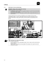
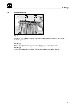
Page 55: ...A E Ei nstellen der Schni tthöhe 0 mod_1196660879619_78 doc 9191 9 1 Adjusting the cutting height Pos 21 4 BA Einstell ung en Mähwer ke Schni tthöhe Schnitthöhe Bild EC 7540 9140 11 mod_1223453474460_78 doc 146635 Fig 26 Pos 21 5 BA Einstell ung en Mähwer ke Schni tthöhe Schnitthöhe größer_geri nger EC280 320 9 mod_1220960304209_78 doc 130271 The cutting height is adjusted via the top link 1 To do...

Page 56: ... factory Pos I basic setting max mowing width Pos II increase overcut 6 cm on each side Pos III increase overcut 12 cm on each side Procedure Connect machine properly to the tractor Lower the machine into working position Lift machine slightly with the tractor s rear hydraulics PTO shaft drive and tractor engine OFF Activate tractor parking brake Remove the ignition key Warning Outrigger arm can s...

Page 57: ...t side of machine Pos I max mowing width Pos II increase overcut by 7 5 cm on each side Pos III increase overcut by 15 cm on each side Procedure The machine must be properly connected to the tractor Bring machine into transport position with tractor rear hydraulics P T O shaft drive and tractor engine OFF Activate tractor parking brake Remove the ignition key WARNING Outrigger arm can slip out Ris...

Page 58: ...serious injuries Check the guard cloths regularly Worn or damaged guard cloths must be replaced The protective equipment on the mowing unit e g cloths and hoods protects against flying stones and similar objects and prevents access to dangerous parts For this reason you must always move them to their protective position before starting work Pos 21 18 BA Ei nstellungen M ähwer ke Seitliche Schutze ...

Page 59: ... 30 Height adjustment determined by side guards Dimension a 440 mm Predefined dimension a on the front guard 1 offers optimum protection against ejected objects Guard is in parallel to the ground A screw driver is used to open the front guards Use the screwdriver to push in the ratchet mechanism Pos 21 21 BA Seitenumbruch 0 mod_1196175311226_0 doc 4165 ...

Page 60: ...jump when mowing yet does not leave any skid marks on the ground Pos 21 25 BA Ei nstellungen M ähwer ke EasyCut Bodendruck Bodendr uckZusatz EC 7540 9140 11 mod_1223453930835_78 doc 146679 The ground pressure can be adjusted through threaded spindles 2 Pos 21 26 BA Ei nstellungen M ähwer ke EasyCut Entl astungsfeder n Entl astungsfeder Bil d Ec7540 9140 10000 42 mod_1272541667536_78 doc 379120 EC8...

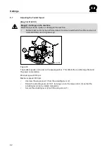
Page 61: ...e throttles 1 2 to adjust the raising and lowering speed of the hydraulic cylinders Pos 21 32 BA Ei nstellungen Dr ossel Drossel 1 Aushubgeschwi ndig keit Arbeits i n Vorgewendestellung 11 mod_1223455172960_78 doc 146790 Throttle 1 Throttle 1 adjusts the lifting speed from working position to headland position Pos 21 33 BA Ei nstellungen Dr ossel Drossel 2 Aushubgeschwi ndig keit Vorgewende Tr ans...

Page 62: ... at a standstill Remove the ignition key Pos 21 38 BA Ei nstellungen M ähwer ke Zetterdr ehzahl Zetterdr ehzahl Bild EC280 320 C V Q 10 mod_1221550487745_78 doc 134924 EC 2 119 600 900 Figure 33 Pos 21 39 BA Ei nstellungen M ähwer ke Zetterdr ehzahl Zetterdr ehzahl einstell en 600 900 11 mod_1223613453645_78 doc 148195 Two tedder speeds can be set on the speed gearbox This affects the conditioning...

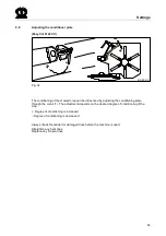
Page 63: ...d_1204713442195_78 doc 72144 EC 032 0 Fig 34 Pos 21 44 BA Ei nstellungen M ähwer ke Einstellung des Aufbereitungsbleches Text EasyC ut 3 mod_1204713282555_78 doc 72125 The conditioning of the mowed crop can be influenced by adjusting the conditioning plate through the crank 1 The adjustment depends on the desired degree of conditioning of the crop Degree of conditioning is increased Degree of cond...

Page 64: ...fahlsicherung Bil d EC 7540 9140 11 mod_1223456077022_78 doc 146857 Fig 35 Pos 21 49 BA Ei nstellungen M ähwer ke EasyCut Pfahlsicher ung Pfahlsicherung allgemein 9 mod_1220961293021_78 doc 130429 In order to protect the disc mower against damages during driving over obstacles it is equipped with a so called pole protection mechanism The optimal setting for the trigger moment takes place in the fa...

Page 65: ...preading with the Cross Conveyor option Pos 21 56 Ü berschriften Ü berschriften 3 A E Einstell ung bei Schwadablage 3 mod_1204713732476_78 doc 72183 9 10 1 Adjustment for Swathing Pos 21 57 BA Ei nstellungen M ähwer ke Schwadbr eite Brei tablag e Ei nstellung der Schwadabl age Bild EC 280 320 CV Q 10 mod_1221551942041_78 doc 134946 EC 0 121 Fig 36 Pos 21 58 BA Ei nstellungen M ähwer ke Schwadbr ei...

Page 66: ...26_78 doc 134990 EC 0 122 Fig 37 Pos 21 62 BA Ei nstellungen M ähwer ke Schwadbr eite Brei tablag e Ei nstellung Br eitabl age Text EC 280 320 C V Q 10 mod_1221552107276_78 doc 135012 The tedder flaps 1 are fully open Mount the deflector plates 2 as shown here Depending on the operating conditions the deflector plates 2 may have to be adjusted to provide for equal distribution across the entire ar...

Page 67: ...ung Br eitabl age Text EC 280 320 C V Q 10 mod_1221552107276_78 doc 135012 The tedder flaps 1 are fully open Mount the deflector plates 2 as shown here Depending on the operating conditions the deflector plates 2 may have to be adjusted to provide for equal distribution across the entire area Pos 21 68 BA Ei nstellungen M ähwer ke Schwadbr eite Brei tablag e Ei nstellung Br eitabl age Text Zusatz ...

Page 68: ...Settings 68 Pos 23 BA Di ese Seite ist bewusst freig elassen worden 1 mod_1201783680373_78 doc 54443 This page has been left blank deliberately Pos 24 BA Sei tenumbruch 0 mod_1196175311226_0 doc 4165 ...

Page 69: ...6281_78 doc 14870 Danger When checking the cutter blades and retaining bolts only sporadically Effect Danger to life injuries or damage to the machine Always check the mowing units for damaged missing or worn blades retaining bolts leaf springs and cutting discs blade drum before starting operation replace any parts that are damaged missing or worn Always replace missing and damaged blades in sets...

Page 70: ... Anzugsdrehmomente 45 mod_1277103093968_78 doc 410970 10 3 Tightening Torques Pos 25 11 BA Wartung Drehmomente Anzugsmomente Dr ehmomente 45 mod_1277102920578_78 doc 410945 The tightening torque MA is stated in Nm unless otherwise indicated A Thread size The stability class can be seen on the head of the screw A Ø 5 6 6 8 8 8 10 9 12 9 MA Nm M 4 2 2 3 4 4 5 1 M 5 4 5 5 9 8 7 10 M 6 7 6 10 15 18 M ...

Page 71: ...OTE The table above applies only to countersunk screws with hexagonal socket heads and metric threading that are tightened by the hexagonal socket head Pos 25 15 Ü berschriften Ü berschriften 3 A E Abweichendes Drehmoment 0 mod_1196950054171_78 doc 15312 10 4 1 Deviating Torque Pos 25 16 BA Wartung Selbstfahr er Gr undmaschine Abweichendes Drehmoment EasyCut 3 mod_1204885737515_78 doc 73465 Screws...

Page 72: ...box 2 x 0 4 Cutter bar EasyCut 7540 2 x 6 0 l Cutter bar EasyCut 9140 2 x 7 0 l Cutter bar EasyCut 9140 CV 2 x 7 0 l Cutter bar EasyCut 10000 Shift 2 x 8 0 l Pos 25 21 BA Wartung Zei tinter valle an den Getri eben 0 mod_1196951919921_78 doc 15373 10 5 1 Oil Level Check and Oil Change Intervals Gearboxes Note Oil level check and oil change gearboxes and lubricating the machine Effect Long expected ...

Page 73: ...Wartung Öl kontrolle_Wechsel Öl wechsel Versi on3 1 mod_1201255900073_78 doc 52826 Oil change For time intervals see Chapter Oil Level Check and Oil Change Intervals Gearboxes Screw out the oil drain plug 2 Collect the used oil in a suitable drip pan Screw in the oil drain plug 2 Top up the oil 3 oil level up to hole 1 Screw the inspection screw 1 and locking screw 3 back in Pos 25 23 5 BA Wartung...

Page 74: ...op up the oil SAE 90 Screw the check screw 1 back in Pos 25 25 5 BA Wartung Öl kontrolle_Wechsel Öl wechsel Versi on1 Bel üftungsfilter 0 mod_1197010026283_78 doc 15747 Oil change For time intervals see Chapter Oil Level Check and Oil Change Intervals Gearboxes Screw out the screw plug 2 Collect the used oil in a suitable drip pan Screw in the screw plug 2 Fill oil 3 oil level up to hole 1 Screw t...

Page 75: ...he inspection screw 1 Oil level up to bore hole 1 If necessary top up the oil SAE 90 Screw the check screw 1 back in Pos 25 27 5 BA Wartung Öl kontrolle_Wechsel Öl wechsel Versi on5 9 mod_1221047052043_78 doc 131562 Oil change For time intervals see Chapter Oil Level Check and Oil Change Intervals Gearboxes Screw out the oil drain plug 1 Collect the used oil in a suitable drip pan Screw in the oil...

Page 76: ...rds Nobody should be in the danger zone around the machine Pos 25 29 6 BA Sicherheit Gefahrenhinweise Mähwerke Schnell rotier ende Messer teller Messertr ommel n_1 0 mod_1197017696736_78 doc 16001 Danger Rapidly rotating cutting discs blade drums Effect Danger to life or serious injuries Switch off the engine and remove the ignition key The cutting discs blade drums continue to run Do not leave th...

Page 77: ...ntenance 77 Pos 25 31 BA Diese Seite ist bewusst freigel assen wor den 1 mod_1201783680373_78 doc 54443 This page has been left blank deliberately Pos 25 32 BA Seitenumbruch 0 mod_1196175311226_0 doc 4165 ...

Page 78: ...c 16361 10 10 1 Cutter Blades Pos 25 33 4 BA Wartung Mähwerke Di e Bohrung der M ähklingen kann sich durch Verschleiß aufweiten 10 mod_1221048982715_78 doc 131675 The borehole on the cutter blades may spread due to wear Pos 25 33 5 BA Sicherheit Gefahrenhinweise Mähwerke Zu g eringe Materialstär ke an den M ähkli ngen_neu 3 mod_1204727167898_78 doc 72588 Danger Insufficient thickness of material o...

Page 79: ...s of material on the retaining bolts Effect Danger to life or serious injuries At every blade changing check the thickness of the holding bolts material Damage or worn retaining bolts must always be replaced by sets on each cutting disc blade drum The material thickness of the retaining bolts must not be less than 14 mm at the weakest point EC 240 0 min 14 mm Fig 44 Pos 25 33 9 BA Seitenumbruch 0 ...

Page 80: ...nger to life or serious injuries At every blade changing check the thickness of the holding bolts material Damage or worn retaining bolts must always be replaced by sets on each cutting disc blade drum The material thickness of the retaining bolts must not be less than 14 mm at the weakest point The material thickness of the leaf spring must not be less than 3 mm at the weakest point EC 239 0 min ...

Page 81: ...n the leaf springs Effect Danger to life or serious injuries Check the leaf springs for damages at least once a day or after contact with foreign objects The abrasion limit of the leaf springs will be achieved if the application seam 1 is worn on one point EC 225 0 1 1 Fig 46 Note Use only original Krone spare parts to replace the leaf springs Pos 25 33 13 BA Seitenumbr uch 0 mod_1196175311226_0 d...

Page 82: ...Discs Blade Drums Effect Danger to life or serious injuries Check the cutting discs or blade drums for damages at least once per day or after contact with foreign objects In case of deformed cuttings discs or drums the dimension of A 48 mm must never be exceeded EC 0 211 A 1 Fig 47 Note The cutting discs or drums must be replaced by Original Krone spare parts only Pos 25 33 15 BA Seitenumbr uch 0 ...

Page 83: ...rums Effect Danger to life or serious injuries The abrasion limit 2 will be achieved if the min material thickness of 3 mm is no longer given EC 226 0 2 2 Fig 48 Note If cutting discs or blade drums show deformations or wear in form of abrasions 2 or similar these components have to be replaced by Original Krone spare parts Pos 25 33 17 BA Seitenumbr uch 0 mod_1196175311226_0 doc 4165 ...

Page 84: ...ade drums continue to run Do not leave the driver s cab until the cutting discs blade drums have come to a complete stop Pos 25 33 20 BA Sicher hei t Gefahrenhi nweise M ähwer ke Sich lösende M ähkli ngen 0 mod_1197269483265_78 doc 16540 Danger Cutter blades coming loose Effect Danger to life or serious injuries After changing the blades check that they fit perfectly and that they can move freely ...

Page 85: ...utting disc Place the locknut 4 on the retaining bolt from above and tighten it firmly tightening torque refer to chapter Torques Repeat the process for all blades After fitting the blades fold the safety device down again Note The cutter blades of anticlockwise rotating cutting discs blade drums are different to those of clockwise rotating ones Make certain the direction of rotation is correct wh...

Page 86: ...uide a new blade 2 onto the retaining bolt and allow the blade key to return upwards After fitting the blades fold the protective device down again Note The cutter blades of anticlockwise rotating cutting discs blade drums are different than those of clockwise rotating ones Make certain the direction of rotation is correct when installing The arrow on the cutter blades must match the direction of ...

Page 87: ...erial to the cutter bar material and to the lining or carry out a trial welding if necessary EC 0 012 Fig 51 Open the welding seams of the old lining Remove the lining Deburr the contact surface EC 252 0 Fig 52 Adapt the new lining 3 Weld short I seams on the upper surface of the cutter bar in the areas marked 1 each should be approx 30 mm Do not weld the edges 2 On the lower surface of the cutter...

Page 88: ...ersicher ung opti onal 4 mod_1213097920976_78 doc 86356 10 13 Rotary hub with shear fuse optional Pos 25 35 2 BA Wartung Mähwerke Schersicherung Bild Mähhol m Aufstellung ec 9140_7540 15 mod_1232447963448_78 doc 173966 Fig 53 Pos 25 35 3 BA Seitenumbruch 0 mod_1196175311226_0 doc 4165 ...

Page 89: ... Eccentric bearing housing anticlockwise threading with identifying groove Pos 25 35 6 BA Wartung Mähwerke Schersicherung Beschrei bung Schersicherung 3 mod_1204205493155_78 doc 69964 For protection against overload on the mowing units the rotary hubs 1 are secured with nuts 2 and shear pins 3 If the machine strikes obstacles for example stones the 2 shear pins in the rotary hub will be sheared of...

Page 90: ...aintenance 90 Pos 25 35 8 BA Wartung Mähwerke Schersicherung Bild Mähhol m Aufstellung ec 10000 Shift 41 mod_1271839589882_78 doc 373449 Fig 54 Pos 25 35 9 BA Seitenumbruch 0 mod_1196175311226_0 doc 4165 ...

Page 91: ...LE Eccentric bearing housing anticlockwise threading with identifying groove Pos 25 35 12 BA Wartung M ähwer ke Schersicher ung Beschr eibung Schersicherung 3 mod_1204205493155_78 doc 69964 For protection against overload on the mowing units the rotary hubs 1 are secured with nuts 2 and shear pins 3 If the machine strikes obstacles for example stones the 2 shear pins in the rotary hub will be shea...

Page 92: ...ion of the bearing housing not observed Effect Damage to the machine Right rotating RE RZ cutting discs and drums always have right handed pinion shafts and nuts no groove mark on the pinion shaft and nut Left rotating LE LZ cutting discs and drums always have left handed pinion shafts and nuts with groove mark on the pinion shaft and nut 1 3 2 8 7 3 4 c d a 9 b EC 255 0 10 3a 3a 3a Fig 55 ...

Page 93: ...e the new shear pins 3 through the hub 1 and shaft 4 Note Note the position of the shear pins Drive the shear pins 3 into the hole from outside until the end of the pin reaches the surface of the hub d he slots of the shear pins 3 must be mounted facing each other horizontally see detail I Install the nut 2 using the special key 10 included with delivery tighten to a tightening torque of 300 Nm In...

Page 94: ...caution the cutting discs continue to run Effect Danger to life injuries or damage to the machine Move the machine to the working position and lower it to the ground Switch off the tractor engine and remove the ignition key Secure the tractor against accidental start up and against rolling Switch off the PTO and disengage it After repair maintenance cleaning work or technical modifications are com...

Page 95: ...e intervals indicated in the drawing with a multi purpose grease Follow the operating instructions of the PTO shaft manufacturer Pos 25 37 8 Abkürzungen Abkürzung en spr achneutral EasyC ut EasyCut 9140 CV EasyC ut 9140 C V C ollect 44 mod_1275545660375_0 doc 392161 EasyCut 9140 CV EasyCut 9140 CV Collect Pos 25 37 9 BA Wartung Mähwerke EasyC ut AM Mähwerke Abschmi eren Gel enkwell e EasyCut 100 h...

Page 96: ...g Hi nweis aus Gründen der Übersicht 2 mod_1202799283498_78 doc 61453 Note To make the illustration easier to read the greasing points have only been shown on one side of the machine The greasing same points are present on the other side of the machine mirror image Pos 25 37 14 BA Wartung M ähwer ke EasyCut AM M ähwer ke Schmi erpl äne Schmierpl an EC 7540 9140 11 mod_1223469752491_78 doc 147217 E...

Page 97: ...od_1202799283498_78 doc 61453 Note To make the illustration easier to read the greasing points have only been shown on one side of the machine The greasing same points are present on the other side of the machine mirror image Pos 25 37 18 BA Wartung M ähwer ke EasyCut AM M ähwer ke Schmi erpl äne Schmierpl an EC 10000 Shi ft 42 mod_1272545001240_78 doc 379173 EC 320 0 Fig 59 Pos 26 BA Sei tenumbru...

Page 98: ...t and on the bearing rings of the guard tubes Pos 27 2 4 BA Einl agerung Alle Gel enkstellen einölen 70 mod_1305633347429_78 doc 638432 Oil all joint points Pos 27 2 5 BA Einl agerung Lackschäden ausbessern blanke Stell en gründlich mit R ostschutzmi ttel konser vier en 70 mod_1305630900253_78 doc 638320 Touch up damaged paint and preserve all uncoated areas thoroughly with rust protection agent P...

Page 99: ...O and disengage it After repair maintenance cleaning work or technical modifications are complete mount all protective coverings and safety devices again properly Avoid skin contact with oils greases cleaning agents and solvents In the event of injuries or burns due to oils cleaning agents or solvents contact a doctor immediately All other safety instructions must also be followed to avoid injurie...

Page 100: ...o make certain they are tight or retighten them if necessary Check all electrical connection cables and the lighting Repair or replace if necessary Check the entire setting of the machine and correct if necessary Re read the operating instructions thoroughly Note Use vegetable oils and greases Pos 27 11 BA Ei nlag erung Rei bkupplung R eibkuppl ung l üften vor der Saison 3 mod_1204731645242_78 doc...

Page 101: ...32297351_78 doc 72885 EC 257 0 1 2 Fig 60 The friction clutch protects the tractor and the machine against damage It is designed with a permanently adjusted turning torque MR The torque is applied on the housing of the friction clutch 2 Venting the friction clutch Tighten the four nuts 1 Block the machine and move the friction clutch manually to the point where it slips through Loosen the nuts aga...

Page 102: ... against accidental start up and against rolling Switch off the PTO and disengage it After repair maintenance cleaning work or technical modifications are complete mount all protective coverings and safety devices again properly Avoid skin contact with oils greases cleaning agents and solvents In the event of injuries or burns due to oils cleaning agents or solvents contact a doctor immediately Al...

Page 103: ... ähwer ke Querförderer Querförderer Text allgemein 10 mod_1222328367161_78 doc 140095 The KRONE cross conveyor is equipped with all the necessary safety devices protective devices However it is not possible to eliminate all the potential hazards on this additional equipment as this would impair the machine s full functional capability You will find corresponding danger warnings which warn against ...

Page 104: ...er ke Querförderer Sicherheitsaufkl eber am Querför der er EasyC ut 7540 9140 74 mod_1308807630933_78 doc 657885 GL 1 1 2 EC800032 1 1 2 3 3 3 3 Fig 62 1 Hazard due to the rapidly circulating conveyor belt Order No 942 200 1 4x 2 939 472 2 Danger in the swivel range of the cross conveyor Order No 939 472 1 2x 3 While parts are moving never reach into areas where there is a risk of being crushed Or...

Page 105: ...n 10 mod_1222331033192_78 doc 140309 Danger Failure to observe adhesive safety stickers on the basic machine Effect Danger to life or serious injuries Observe also the adhesive safety stickers on the basic machine see in chapter on Safety Position of the Adhesive Safety Stickers on the Machine Pos 31 11 BA Seitenumbruch 0 mod_1196175311226_0 doc 4165 ...

Page 106: ...od_1223473316116_78 doc 147379 GL EC800033 1 1 2 Fig 63 1 942 320 0 2x 600 mm 2 939 475 1 2x Pos 31 14 BA Sonderausstatung EasyC ut AM M ähwer ke Querför der er Hinweis Lage der Hinweisaufkl eber an der M aschine beachten 10 mod_1222331206426_78 doc 140373 Caution Failure to observe general information labels on the basic machine Effect Damage to the machine Observe also the general information la...

Page 107: ...the machine is moved into transport position the cross conveyors 3 must be moved into working position This ensures the cross conveyor belts cannot collide with each other during the changeover to transport position Pos 31 18 Ü berschriften Ü berschriften 3 F J H ydr auli k 35 mod_1257935807425_78 doc 334930 14 7 1 Hydraulics Pos 31 19 BA Sonderausstatung EasyC ut AM M ähwer ke Querför der er H yd...

Page 108: ...rför der er Geschwindig kei tsregler QFB Bil d EC 9140 CV 11 mod_1223527197539_78 doc 147537 1 4 2 3 EC800038 Fig 65 Pos 31 25 BA Sonderausstatung EasyC ut AM M ähwer ke Querför der er Geschwindig kei t der Tr ansportbänder einstell en 11 mod_1223475295850_78 doc 147491 The rotary potentiometer 4 can be used to adjust the speed of the conveyor belts Clockwise faster Anticlockwise slower Pos 31 26 ...

Page 109: ...t a distance of a 1000 mm Use the adjustment screws 3 to tighten the conveyor belt until the marks have a dimension of a 1006 mm Tighten the bearing bolts 4 on the right and left see in Maintenance chapter Tightening Torques Pos 31 28 BA Sonderausstatung EasyC ut AM M ähwer ke Querför der er Leiste am Querföderband ver bog en 44 mod_1275989250656_78 doc 394468 14 9 Bar on cross conveyor is bent 1 ...

Page 110: ...d consult appropriate information from a competent medical source Check the hydraulic hose lines at regular intervals and replace them if damaged or worn The replacement lines must comply with the requirements of the device manufacturer Ensure that all line connections are tight before the pressure in the system builds up again Repair work on the hydraulic system must only be performed by authoris...

Page 111: ... 10 mod_1222335092723_78 doc 140522 Pressure is supplied to the on board hydraulic system of the machine through its own hydraulic pump 1 The hydraulic pump 1 is connected to the lower part of the main gearbox by a flange and requires no maintenance Pos 31 39 BA Wartung Ölsorte nicht mischen 10 mod_1222334992520_78 doc 140501 Note Do not mix different types of oil Effect Damage to the machine Neve...

Page 112: ...he ventilation filter 2 and insert it again completely Pull out the ventilation filter 2 again The oil level must lie between the min and max mark Top off with hydraulic oil if necessary Screw in and tighten the ventilation filter 2 Pos 31 44 Ü berschriften Ü berschriften 3 K O Öl wechsel 0 mod_1197021941955_78 doc 16139 14 10 4 Oil change Pos 31 45 BA Sonderausstatung EasyC ut AM M ähwer ke Querf...

Page 113: ...when changing the filter Properly dispose of filter cartridge that was removed Replace the hydraulic oil filter before every season but at least once year Unscrew the screw cover 1 Lift the filter insert 2 and allow hydraulic oil to drip out Remove the filter insert and dispose of it correctly Moisten the seal surface of the new filter insert with oil and set it in place Tighten the screw cover 1 ...

Page 114: ...1133_78 doc 147603 15 1 1 Without cross conveyor belt Pos 33 4 BA Anhang EasyCut H ydrauli kschal tpl an H ydr aulikschalpl an ohne Quer föder band 11 mod_1223527962273_78 doc 147648 150 100 138 00 Fig 71 Pos 33 5 Überschriften Überschriften 3 K O mit Querförderband 11 mod_1223527916633_78 doc 147625 15 1 2 With cross conveyor belt Pos 33 6 BA Anhang EasyCut H ydrauli kschal tpl an H ydr aulikscha...

Page 115: ...5 2 Electrical circuit diagram Pos 33 9 BA Anhang EasyCut Schaltpläne EC 7540 9140 11 mod_1223631730676_78 doc 148415 You will find the circuit diagrams listed below in the Appendix 1 Circuit diagram with cross conveyor belt 150 100 095 2 Circuit diagram without cross conveyor belt 150 100 096 Ende der Stückliste ...

Page 116: ...30 rt 12 ge 11 ge X2 E gr 11a ge 2 ge 11b ge 3 ge 12a ge 4 ge 12b ge Masse von der Batterie Batterie 12V von der Batterie Batterie Blatt Nr 1 2 3 4 5 6 7 8 Anlage EasyCut 7540 9140 9140 CV Kurze Albers 1 2 3 4 5 6 7 8 08 10 2007 24 08 2004 Ers durch Ers für Datum Letzte Änderung Erstellt A 4 Fach Ort 1 1 Bearb Änderung 150 100 095 000 01 Bl von Anz Urspr Doc Nr D24 B C 1 ...

Page 117: ...V 0V 0V 0V Poti Poti Ausg A1 K1 Ausg K1 N1 GND XP K X2 J X2 1 X3 2 X3 braun br grün gr 30 rt rot rt 31 sw 13 ge 12 ge 11 br gelb ge blau bl gruen gr weiss ws 11a ge 2 ge 11b ge 3 ge 12a ge 4 ge 12b ge 1 ge 1a ge 13a ge 1b ge 13b ge 7 ge 8 ge 9 ge Masse von der Batterie der Batterie 12V von der Batterie Batterie Blatt Nr 1 2 3 4 5 6 7 8 Anlage EasyCut 9140 CV QFB Kurze Albers 1 2 3 4 5 6 7 8 08 10 ...

Page 118: ...ing the electrical controls 36 Connecting the hydraulic lines 34 Contact 8 Cross conveyor 103 Cutter Blades 78 D Dangers in Case of Non compliance with the Safety Instructions 13 Detaching the machine 53 Deviating Torque 71 Driving and Transport 41 E Electrical circuit diagram 115 F Filling Quantities and Lubricant Designations 110 Filling Quantities and Lubrication Designations for Gearboxes 72 F...

Page 119: ... 24 PTO operation 16 PTO shaft 31 38 95 Purpose of Use 8 R Re Ordering the Adhesive Safety and Information Labels 27 Replacing the hydraulic oil filter 113 Replacing the linings 87 Rotary hub with shear fuse optional 88 S Safety 12 Safety Instructions and Accident Prevention Regulations 14 Safety Instructions on the Machine 103 Safety conscious work practices 13 Setting Conveyor Belt 109 Setting o...

Page 120: ...Bernard Krone GmbH Heinrich Krone Straße 10 D 48480 Spelle Postfach 11 63 D 48478 Spelle Phone 49 0 59 77 935 0 Fax 49 0 59 77 935 339 Internet http www krone de eMail info ldm krone de konsequent kompetent 1 Jul 2009 ...

Reviews: