Maintenance - hydraulic system
181
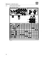
The following table shows which valves must be released by screwing in the setting screws to
execute the corresponding function.
Carry out the steps in the following table very exactly in order to raise the machine to transport
position. After each step, screw the setting screws out again.
1.
Fold the right-hand lateral mowing unit in headland position (Y11).
2.
Fold the left-hand lateral mowing unit in headland position (Y09).
3.
Lower the left-hand cross conveyor (Y1,Y16.1,Y16.2).
4.
Lower the right-hand cross conveyor (Y1,Y17.1,Y17.2).
5.
Deploy the left-hand lateral mowing unit (Y2, Y24.1, Y24.2).
6.
Deploy the right-hand lateral mowing unit (Y2, Y22.1, Y22.2).
7.
Fold the lateral mowing units from the headland position to transport position.
(Y2, Y18.1, Y18.2, Y19)
8.
Retract the left-hand lateral mowing unit (Y1, Y24.1, Y24.2).
9.
Retract the right-hand lateral mowing unit (Y2, Y22.1, Y22.2).
Pos: 83.15 /Layout Module /---------------Seitenumbruch---------------- @ 0\mod_1196175311226_0.docx @ 4165 @ @ 1

