background image

Special equipment

76

Pos : 31.6 /Übersc hrift en/Übersc hrift en 3/A-E/Anbau der Abst ellst ütz en @ 39\ mod_1268206739480_78.doc x @ 358511 @ 2 @ 1

14.3.2

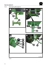
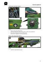
Attaching the parking supports

Pos : 31.7 /Bei pac ks/ Eas yCut /Abst ellst ütz en Bei pac k 150 xxx xxx xx/ Anbau der Abst ellstützen Bild @ 58\ mod_1296742026637_78. doc x @ 554064 @ 2 @ 1

a

EC-348-0

II

I

III

IV

a

1

9 8

10 9

5

7

4
3

6

2

2

1

Fig.46

Pos : 31.8 /BA/---------------Seitenumbruc h---------------- @ 0\ mod_1196175311226_0. doc x @ 4165 @ 3 @ 1

Summary of Contents for EasyCut R 280

Page 1: ...O r i g i n a l o p e r a t i n g i n s t r u c t i o n s Disc Mower EasyCut R 280 EasyCut R 320 from serial no 856 285 Order no 150 000 145 02 en 19 12 2012 ...

Page 2: ...ning Managing Director is authorised to compile the technical documents Spelle 08 11 11 Dr Ing Josef Horstmann Managing Director Design and Development Year of manufacture Machine No Pos 2 BA Vor wort Sehr geehrter Kunde 0 mod_1195626300326_78 docx 905 1 Dear customer Dear customer You have now received the operating instructions for the KRONE product which you have purchased These operating instr...

Page 3: ...ulations 12 4 4 Attached devices 13 4 5 PTO operation 14 4 6 Hydraulic system 15 4 7 Maintenance 15 4 8 Unauthorised Conversion Modification and Spare Parts Production 16 4 9 Inadmissible Modes of Operation 16 4 10 Working in the vicinity of power transmission lines 16 4 11 Introduction 17 4 12 Position of the Adhesive Safety Stickers on the Machine 18 4 12 1 Re Ordering the Adhesive Safety and In...

Page 4: ...1 Deviating Torque 47 10 5 Storage compartment 48 10 6 Filling Quantities and Lubrication Designations for Gearboxes 48 10 6 1 Oil Level Check and Oil Change Intervals Gearboxes 48 10 7 Main gearbox 49 10 8 Mower Drive Gearbox 50 10 9 Oil level check and oil change on the cutter bar 51 10 9 1 Oil change 51 10 9 2 Checking the oil level 51 10 10 Checking the Cutter Blades and Blade Holder 52 10 10 ...

Page 5: ...4 1 Special Safety Instructions 74 14 2 Adjusting Skids 74 14 3 Lowering the machine into transport position on parking supports accessories kit 75 14 3 1 Scope of the accessories kit 75 14 3 2 Attaching the parking supports 76 14 4 Hydraulic spring compensation optional 78 14 4 1 Scope of the accessories kit 78 14 4 2 Mounting 79 Pos 6 BA Seitenumbr uch 0 mod_1196175311226_0 docx 4165 1 ...

Page 6: ...Cut 3 mod_1204546850246_78 docx 70549 1 Note In the operating instructions which follow the disc mower will also be referred to as the machine Pos 7 4 BA Vor wort Beachten Sie für Maschi ne 0 mod_1195626904076_78 docx 944 1 Please note The operating instructions are part of your machine Only operate this machine after you have been trained to do so and according to these instructions It is essenti...

Page 7: ...gszweck Mäher 3 mod_1204547495418_78 docx 70590 1 The EasyCut disc mower is used for cutting crops growing on the ground except maize Pos 9 4 BA Ei nleitung Gültigkeit EasyC ut EasyC ut R 280 320 73 mod_1308578262680_78 docx 655774 2 1 3 2 Validity These operating instructions apply to disc mowers of the series EasyCut R 280 and EasyCut R 320 Pos 9 5 Ü berschriften Ü berschriften 3 A E Anspr echpa...

Page 8: ...Questions and Orders Year Mach No Type Note The entire identification plate represents a legal document and should not be altered or rendered illegible When asking questions concerning the machine or ordering spare parts be sure to provide type designation machine number and the year of manufacture of the relevant machine To ensure that these data are always available we recommend that you enter t...

Page 9: ...ications to the machine may affect the properties of the machine or disrupt proper operation For this reason unauthorised modifications shall exclude any liability of the manufacturer for consequential damage Pos 9 13 BA Einl eitung Technische D atenTechnische D aten 0 mod_1195566374865_78 docx 594 2 1 3 6 Technical data All information illustrations and technical data in these operating instructi...

Page 10: ...274714 2 1 4 2 Identification of the hazard warnings Danger DANGER Type and source of the hazard Effect Danger to life or serious injuries Measures for hazard prevention Warning WARNING Type and source of the hazard Effect Injuries serious material damage Measures for hazard prevention Caution CAUTION Type and source of the hazard Effect Property damage Measures for risk prevention Pos 11 4 BA Sic...

Page 11: ...ructions are not respected this could result in the forfeiture of any claims for damages Failure to follow the safety instructions could result for example in the following hazards Endangering of persons due to not protected working areas Breakdown of important machine functions Failure of prescribed methods for repair and maintenance Endangering of persons due to mechanical and chemical effects D...

Page 12: ...s 11 Use extreme caution when attaching or detaching implements onto or from the tractor 12 Always attach ballast weights properly to the fixing points provided 13 Observe permitted axle loads gross weight and transport dimensions 14 Check and attach transport equipment such as lighting warning devices and protective equipment 15 Actuating mechanisms cables chains linkages etc for remote controlle...

Page 13: ...n when attaching or detaching implements onto or from the tractor 2 Couple the respective application devices to the appropriate couplings e g three point suspension only and secure them in a way transport use that excludes inadvertent lifting or lowering of the device 3 When using three point linkage the attachment categories of the tractor and the device e g PTO speed hydraulic system must be co...

Page 14: ...shaft make sure that no person is in the danger zone of the device 10 Never switch on the PTO if the engine is switched off 11 No one should be in the vicinity of the rotating PTO or PTO shaft when the PTO is in use 12 Always switch off the PTO shaft when the angle is too large or the PTO shaft is not required 13 Caution After disengaging the PTO danger due to the flywheel running on Keep away fro...

Page 15: ...d replace them if damaged or worn The new hoses must fulfill the technical requirements set by the manufacturer of the implement Pos 11 6 13 Ü berschriften Ü berschriften 2 U Z Wartung 33 mod_1254222340957_78 docx 318599 2 1 4 7 Maintenance Pos 11 6 14 BA Sicherheit Wartung Wartung Pos 1 ohne Schwung mass Feststell bremse anzi ehen 17 mod_1236239576347_78 docx 203270 1 1 Always make certain that t...

Page 16: ...d use of the operating instructions The limit values listed in the data charts should not be exceeded under any circumstances Pos 11 7 BA Sicher heit Ar beiten i m Ber eich von H ochspannungsleitungen 11 mod_1223357468516_78 docx 145505 2 1 4 10 Working in the vicinity of power transmission lines 1 Always take great care when working under or in the vicinity of power transmission lines 2 Ensure th...

Page 17: ...d what they mean is given below Pos 11 10 BA Sicherheit Ü berarbeitete Warnhinweise Gefahr Beschädigte oder unl esbare Aufkl eber 2012 07 26 14 29 51 0 mod_1195567214115_78 docx 674 1 Danger Danger zone of the machine Effect Danger to life or serious injuries Immediately replace damaged or illegible adhesive labels Following repair work always attach appropriate adhesive safety stickers to all the...

Page 18: ... 007 982 0 1x a Before placing the machine into operation read the operating instructions and safety instructions Both must be heeded b Keep the stipulated safe distance from power transmission lines c The PTO speeds must not exceed 540 rpm The operating pressure of the hydraulic system must not exceed 200 bar 1a 1b 1c MAX 540 min MAX 200 bar 2 While parts are moving never reach into areas where t...

Page 19: ...e Wait until they have come to a complete stop b Move the safety devices into protective position prior to start up c When the machine is running keep your distance 939 410 2 STOP a 939 572 0 b 942 197 1 c 5 The accumulator is under gas and oil pressure The repair is only possible by exchanging the complete unit Order No 939 529 0 1x Pos 11 14 BA Seitenumbr uch 0 mod_1196175311226_0 docx 4165 1 ...

Page 20: ...dhesive safety and information label is assigned an order number and can be ordered directly from the manufacturer or from an authorized dealer see Section Contact 4 12 2 Affixing the Adhesive Safety and Information Labels Note Affixing an adhesive label Effect Adhesion of the label The surface for affixing the adhesive label must be clean and free of dirt oil and grease Pos 13 BA Seitenumbruch 0 ...

Page 21: ...Remove the ignition key Secure the machine against the possibility of rolling back Pos 14 6 BA Sicher heit Gefahr enhi nweise Gefahr Fehl erhafter Zusammenbau 1 mod_1202224212591_78 docx 58171 1 Danger Incorrect assembly Effect Danger to life serious injuries or serious damage to the machine Only authorised service centres may assemble the machine The machine must be assembled with special care Al...

Page 22: ...nkte Kuppelpunkte Text EC 320 1 58 mod_1297063817994_78 docx 554787 2 1 There are 2 possibilities for attaching the mowing unit I The steerable pinions are designed according to cat II Normally the mowing unit is hooked to the tractor in pos 1 When using broad tractors or when working in combination with front mowing units working width of approx 2 8 3 2 m the mowing unit should be attached at pos...

Page 23: ...t the machine from swivelling out during transport or work If the lower suspension arms 1 are equipped with catch hooks the following items must be taken into consideration Especially in the headland position high forces develop in the lower suspension arm bolts 3 that act upwards in the left hand hook For this reason the catch hooks must be in a flawless condition Additionally the catch hooks mus...

Page 24: ...chanism is triggered Coverage of at least 200 mm shift length must be ensured for the special section tubes and guard tubes in every operating position For additional operating instructions refer to the operating instructions of the PTO shaft manufacturer Pos 14 23 BA Sicherheit Gel enkwell e Achtung Schwenkber eich Freir aum über prüfen 9 mod_1220536308930_78 docx 126898 2 1 Caution Swivel range ...

Page 25: ...er suspension arm bolts 3 that act upwards in the left hand hook For this reason the catch hooks must be in a flawless condition Additionally the catch hooks must be secured in the provided locking hole 4 against unwanted opening after the machine has been connected to the tractor Pos 16 4 BA Sicher heit Gefahr enhi nweise M ähwer ke War nung Achslasten Beei nträchtigung der Lenkfähig kei t 9 mod_...

Page 26: ...1 2 3 4 1 Fig 6 Pos 16 8 BA Inbetriebnahme Ersti nbetri ebnahme EasyCut Ankuppeln Text EC 280 320 280 320C V Q 9 mod_1220537421383_78 docx 126948 3 1 Attach the machine onto the lower suspension arm 1 of the tractor Hook the top link 2 into the upper hole of the 3 point support Pos 16 9 BA Seitenumbruch 0 mod_1196175311226_0 docx 4165 1 1 ...

Page 27: ...pressurise prior to uncoupling the hydraulic hoses and working on the hydraulic system Check the hydraulic hose lines at regular intervals and replace them if damaged or worn The replacement hoses must fulfil the technical requirements set by the equipment manufacturer Pos 16 13 Ü berschriften Ü berschriften 3 A E Anschluss der H ydrauli kleitungen 0 mod_1199777037794_78 docx 34244 1 6 2 2 Connect...

Page 28: ...t come into contact with the tractor tyres Note chafing areas or points of contact Pos 16 18 BA Inbetri ebnahme EasyCut H ydrauli k H ydrauli kanschluss Bild EC 320 N eue Generation 58 mod_1296658290463_78 docx 552744 2 1 EC 330 0 3 1 Fig 7 Pos 16 19 BA Inbetri ebnahme EasyCut H ydrauli k Steuergerät 1xEW 10 mod_1221486740745_78 docx 134020 3 1 A single action control unit is required on the tract...

Page 29: ...een attached Replace damaged protective devices immediately Attach the safety chain of the PTO shaft so that the guard tube does not rotate simultaneously with the PTO shaft Pos 16 25 BA Sicherheit Gel enkwell e Gefahr Falsche Zapfwellendr ehzahl 540 U mi n 9 mod_1220868351329_78 docx 128138 2 1 Danger Incorrect PTO speed Effect Danger to life serious injuries or damage to the machine This machine...

Page 30: ...6 32 BA Inbetri ebnahme EasyCut Anbau Gel enkwell e Zwischeng elenkwell eZwischengel enkwell e Bil d EC 320 N eue Generation 78 mod_1314263618497_78 docx 695880 1 EC 386 0 2 3 Fig 9 Pos 16 33 BA Inbetri ebnahme EasyCut Anbau Gel enkwell e Zwischeng elenkwell eZwischengel enkwell e ohne Freil auf Text EC 280 R 320 R 78 mod_1314262196417_78 docx 695821 1 The intermediate PTO shaft for the mowing uni...

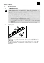
Page 31: ...it in place with the bolt 1 Pos 16 40 BA Bedienung EasyC ut Abstellstütze Vi er Stützen optional Überschrift 58 mod_1296816723926_78 docx 554520 1 6 6 1 Four supports optional Pos 16 41 BA Bedienung EasyC ut Abstellstütze Vi er Stützen angehoben Bild EC 320 Neue Gener ati on 58 mod_1296816797691_78 docx 554548 2 1 1 2 1 2 3 EC 349 0 1 3 1 Fig 11 Pos 16 42 BA Bedienung EasyC ut Abstellstütze Abstel...

Page 32: ...erious damage to the machine In transport position always make certain that the locking mechanism 2 has snapped into place Pos 18 4 Überschriften Überschriften 2 U Z Von Ar bei tsstellung in Transportstell ung 2 mod_1202466246542_78 docx 59681 3 1 7 1 Switching from working position to transport position Pos 18 5 BA Sicher heit Fahren und Transport Hochschwenken des Mähwer ks i n Transpor tstellun...

Page 33: ...nto transport position and lock it into position with the bolt see chapter on start up entitled Swivelling the parking support into transport position To release the locking mechanism 2 pull the actuating rope 3 up from the tractor Actuate the control valve for the hydraulic cylinder on the tractor The mowing unit lifts up into the transport position Lower the locking 2 and make certain that the o...

Page 34: ...e mowing unit is resting on the ground Pos 20 4 BA Sicher heit Gefahr enhi nweise M ähwer ke Gefahr Verriegel ung prüfen EC 280 320 9 mod_1220879526173_78 docx 128463 2 1 Danger Check whether the locking mechanism 1 is folded down completely Effect Danger to life serious injuries or serious damage to the machine The folded down locking mechanism secures the mowing unit against inadvertent lifting ...

Page 35: ... not carry out work on the disc mower until the PTO has been switched off the engine has been turned off and the ignition key has been removed Secure the tractor against accidental start up and against rolling Support the lifted cutter bar Never step under suspended loads Before using the machine always check the protective devices for damage Replace damaged protective devices immediately Safe ope...

Page 36: ...mowing unit e g cloths and hoods protects against flying stones and similar objects and also prevents access to dangerous parts Because of this you must always move it to its protective position before starting work Fold the side plate s down and secure with twist locks before use Pos 20 15 BA Bedienung EasyC ut Schutze Schutzeinrichtung her unter kl appen Bil d EC 320 1 58 mod_1297064163294_78 do...

Page 37: ...sition Pos 20 22 BA Bedienung EasyC ut Abstellstütze Abstellstütze angehoben 10 mod_1221638250775_78 docx 135670 2 1 Lift the parking support 2 into the working position of the disc mower and lock it in place with the bolt 1 Pos 20 23 BA Bedienung EasyC ut Abstellstütze Vi er Stützen optional Überschrift 58 mod_1296816723926_78 docx 554520 1 8 3 1 Four supports optional Pos 20 24 BA Bedienung Easy...

Page 38: ...in the front area 1 and the rear area 2 are at the same level a ca 0 mm The adjustment is made through the height adjustment of the lower suspension arms on the tractor Pos 20 32 Ü berschriften Ü berschriften 2 U Z Vorgewendestell ung 0 mod_1196414916041_78 docx 8116 1 8 4 Headland Position Pos 20 33 BA Sicherheit Vorg ewendestell ung Gefahr Vorgewende M ähwer ke EC 280 320 9 mod_1220881723360_78 ...

Page 39: ...se to and disconnecting it from the hydraulic system of the tractor the tractor system as well as the machine system must be depressurised Move the appropriate control valves into the flow position When detaching the machine do not walk between the tractor and the machine Pos 20 38 BA Sicherheit Gefahrenhinweise Ei nstellar beiten Ei nstellungenGefahr Ei nstellung an den Entl astungsfeder n nur i ...

Page 40: ...ydraulics lower the machine to the ground Pos 20 44 BA Bedienung EasyC ut Abstellstütze Vi er Stützen optional Überschrift 58 mod_1296816723926_78 docx 554520 22 1 8 5 1 Four supports optional Pos 20 45 BA Bedienung EasyC ut Abstellstütze Achtung Ki ppg efahr 58 mod_1297065492192_78 docx 554954 3 1 CAUTION Danger of tipping Machine may be lowered into transport position only with additionally atta...

Page 41: ...l n Text EC 280 320 9 mod_1220884945345_78 docx 129009 1 Remove the PTO shaft 1 from the tractor and place it onto the storage surface 2 Disconnect the hydraulic hose 3 from the tractor set the dust cap in place Remove the synthetic rope 4 from the tractor Release the upper link and pull out the bolt on the machine side or unhook the upper link Pull off the lower suspension arm release the catch h...

Page 42: ...Überschriften 2 A E Ei nstellen der Schnitthöhe 0 mod_1196660879619_78 docx 9191 1 9 1 Adjusting the cutting height Pos 22 4 BA Einstell ung en Mähwer ke Schni tthöhe Schnitthöhe Bild EC 320 1 58 mod_1296728609281_78 docx 553507 3 1 EC 340 0 Fig 21 Pos 22 5 BA Einstell ung en Mähwer ke Schni tthöhe Schnitthöhe größer_g eringer EC280 320 9 mod_1220960304209_78 docx 130271 1 The cutting height is ad...

Page 43: ...round pressure for the cutter bar is adjusted to local conditions by means of the compensation springs In order to protect the sward the load on the mowing spar must be relieved so that it does not jump when mowing yet does not leave any skid marks on the ground Pos 22 10 BA Ei nstellungen M ähwer ke EasyCut Entl astungsfeder n Entl astungsfeder Bil d Ec 280 320 1 58 mod_1296731267645_78 docx 5535...

Page 44: ...l d EC 320 1 58 mod_1296731365769_78 docx 553624 2 1 Fig 23 Pos 22 17 BA Ei nstellungen M ähwer ke EasyCut Pfahlsicher ung Pfahlsicherung allgemein 9 mod_1220961293021_78 docx 130429 1 In order to protect the disc mower against damages during driving over obstacles it is equipped with a so called pole protection mechanism The optimal setting for the trigger moment takes place in the factory Pos 22...

Page 45: ...maged missing or worn Always replace missing and damaged blades in sets to prevent unbalanced rotation Never mount unevenly worn blades on a drum disc Whenever a blade is changed also inspect the fasteners and replace them if necessary Pos 24 5 Überschriften Überschriften 3 P T Probelauf 0 mod_1196833698843_78 docx 15023 22 1 10 1 1 Test run Pos 24 6 BA Sicher heit Gefahr enhi nweise M ähwer ke Ge...

Page 46: ...screw A Ø 5 6 6 8 8 8 10 9 12 9 MA Nm M 4 2 2 3 4 4 5 1 M 5 4 5 5 9 8 7 10 M 6 7 6 10 15 18 M 8 18 25 36 43 M 10 29 37 49 72 84 M12 42 64 85 125 145 M14 100 135 200 235 M14x1 5 145 215 255 M 16 160 210 310 365 M16x1 5 225 330 390 M 20 425 610 710 M 24 730 1050 1220 M 24x1 5 350 M 24x2 800 1150 1350 M 27 1100 1550 1800 M 27x2 1150 1650 1950 M30 1450 2100 2450 NOTE The table above does not apply to ...

Page 47: ...The table above applies only to countersunk screws with hexagonal socket heads and metric threading that are tightened by the hexagonal socket head Pos 24 15 Ü berschriften Ü berschriften 3 A E Abweichendes Drehmoment 0 mod_1196950054171_78 docx 15312 22 1 10 4 1 Deviating Torque Pos 24 16 BA War tung Selbstfahr er Gr undmaschine Abweichendes Drehmoment EasyCut 3 mod_1204885737515_78 docx 73465 3 ...

Page 48: ...the cutter bar Pos 24 24 BA War tung Tabellen_Füll mengen M ähwer ke Technische D aten Betriebsstoffe Füll meng en EC R 280 320 73 mod_1308580315066_78 docx 655970 3 1 Filling Quantity filtered oils Bio degradable lubricants litres Brand name Brand name Main gearbox 0 5 l SAE 90 On request Mower Drive Gearbox 0 3 l Cutter bar EasyCut R 280 6 0 l Cutter bar EasyCut R 320 7 0 l Pos 24 25 BA War tung...

Page 49: ..._ALTÖl wechsel Version4 9 mod_1221045564153_78 docx 131453 3 1 Oil change For time intervals see Chapter Oil Level Check and Oil Change Intervals Gearboxes Screw out the oil drain plug 2 Collect the used oil in a suitable drip pan Screw in the oil drain plug 2 Top up the oil 1 Pos 24 27 6 BA Wartung Öl kontroll e_Wechsel Ölqualität Öl menge siehe Kapitel 0 mod_1197007859486_78 docx 15531 3 1 Oil q...

Page 50: ...rew the check screw 1 back in Pos 24 29 4 BA Wartung Öl kontroll e_Wechsel Öl wechsel_ALTÖl wechsel Version5 9 mod_1221047052043_78 docx 131562 2 1 Oil change For time intervals see Chapter Oil Level Check and Oil Change Intervals Gearboxes Screw out the oil drain plug 1 Collect the used oil in a suitable drip pan Screw in the oil drain plug 1 Top up the oil 2 oil level up to hole 1 Pos 24 29 5 BA...

Page 51: ...r guards Nobody should be in the danger zone around the machine Pos 24 31 6 BA Sicherheit Gefahrenhinweise Mähwer ke Gefahr Schnell rotier ende Messerteller Messertr ommel n_1 0 mod_1197017696736_78 docx 16001 2 1 Danger Rapidly rotating cutting discs blade drums Effect Danger to life or serious injuries Switch off the engine and remove the ignition key The cutting discs blade drums continue to ru...

Page 52: ...ck cutter blades at least once per day and check retaining bolts every time you change the blades or after contact with foreign objects Immediately replace missing or damaged cutter blades and cutter blade retainers Pos 24 33 3 BA Wartung Mähwerke N ach Beendigung Schutz in Schutzstell ung bringen EC 320 N eue Generaton 58 mod_1296735673222_78 docx 553843 1 2 Fig 28 To inspect and fit the blades f...

Page 53: ...8_78 docx 72588 1 Danger Insufficient thickness of material on the cutter blades Effect Danger to life or serious injuries The cutter blades must be replaced at the latest when the wear limit is reached see mark 1 on the cutter blade dimension a less than or equal to 7 mm Pos 24 33 8 BA Wartung Mähwerke M ähklingen beidseitig verwenbar_neu 3 mod_1204728012601_78 docx 72608 2 1 a EC 253 0 1 Fig 29 ...

Page 54: ... of material on the retaining bolts Effect Danger to life or serious injuries At every blade changing check the thickness of the holding bolts material Damage or worn retaining bolts must always be replaced by sets on each cutting disc blade drum The material thickness of the retaining bolts must not be less than 14 mm at the weakest point EC 240 0 min 14 mm Fig 30 Pos 24 33 11 BA Seitenumbruch 0 ...

Page 55: ...anger to life or serious injuries At every blade changing check the thickness of the holding bolts material Damage or worn retaining bolts must always be replaced by sets on each cutting disc blade drum The material thickness of the retaining bolts must not be less than 14 mm at the weakest point The material thickness of the leaf spring must not be less than 3 mm at the weakest point EC 239 0 min...

Page 56: ... the leaf springs Effect Danger to life or serious injuries Check the leaf springs for damages at least once a day or after contact with foreign objects The abrasion limit of the leaf springs will be achieved if the application seam 1 is worn on one point EC 225 0 1 1 Fig 32 Note Use only original Krone spare parts to replace the leaf springs Pos 24 33 15 BA Seitenumbruch 0 mod_1196175311226_0 doc...

Page 57: ...scs Blade Drums Effect Danger to life or serious injuries Check the cutting discs or blade drums for damages at least once per day or after contact with foreign objects In case of deformed cuttings discs or drums the dimension of A 48 mm must never be exceeded EC 0 211 A 1 Fig 33 Note The cutting discs or drums must be replaced by Original Krone spare parts only Pos 24 33 17 BA Seitenumbruch 0 mod...

Page 58: ...drums Effect Danger to life or serious injuries The abrasion limit 2 will be achieved if the min material thickness of 3 mm is no longer given EC 226 0 2 2 Fig 34 Note If cutting discs or blade drums show deformations or wear in form of abrasions 2 or similar these components have to be replaced by Original Krone spare parts Pos 24 33 19 BA Seitenumbruch 0 mod_1196175311226_0 docx 4165 33 1 ...

Page 59: ...de drums continue to run Do not leave the driver s cab until the cutting discs blade drums have come to a complete stop Pos 24 33 22 BA Sicher hei t Gefahrenhi nweise M ähwer ke Gefahr Sich lösende M ähkli ngen 0 mod_1197269483265_78 docx 16540 1 1 Danger Cutter blades coming loose Effect Danger to life or serious injuries After changing the blades check that they fit perfectly and that they can m...

Page 60: ...he cutting disc Place the locknut 4 on the retaining bolt from above and tighten it firmly tightening torque refer to chapter Torques Repeat the process for all blades After fitting the blades fold the safety device down again Note The cutter blades of anticlockwise rotating cutting discs blade drums are different to those of clockwise rotating ones Make certain the direction of rotation is correc...

Page 61: ... Guide a new blade 2 onto the retaining bolt and allow the blade key to return upwards After fitting the blades fold the protective device down again Note The cutter blades of anticlockwise rotating cutting discs blade drums are different than those of clockwise rotating ones Make certain the direction of rotation is correct when installing The arrow on the cutter blades must match the direction o...

Page 62: ...ial to the cutter bar material and to the lining or carry out a trial welding if necessary EC 0 012 Fig 37 Open the welding seams of the old lining Remove the lining Deburr the contact surface EC 252 0 Fig 38 Adapt the new lining 3 Weld short I seams on the upper surface of the cutter bar in the areas marked 1 each should be approx 30 mm Do not weld the edges 2 On the lower surface of the cutter b...

Page 63: ...ance 63 Pos 24 35 BA Diese Seite ist bewusst freigel assen wor den 1 mod_1201783680373_78 docx 54443 1 This page has been left blank deliberately Pos 24 36 BA Seitenumbr uch 0 mod_1196175311226_0 docx 4165 1 1 ...

Page 64: ...920976_78 docx 86356 1 10 13 Rotary hub with shear fuse optional Pos 24 37 2 BA Wartung Mähwerke Schersicherung Bil d Mähhol m Aufstellung EC R 280 Bild Mähhol m Aufstellung EC R 280 320 C V EC F 320 C V 147 mod_1361180309624_78 docx 1319551 2 1 Fig 39 Pos 24 37 3 BA Seitenumbr uch 0 mod_1196175311226_0 docx 4165 2 1 ...

Page 65: ...ntifying groove Pos 24 37 6 BA Wartung Mähwerke Schersicherung Beschrei bung Schersicher ung R E LE 99 mod_1330074896634_78 docx 889358 1 For protection against overload on the mowing units the rotary hubs 1 are secured with nuts 2 and shear pins 3 If the machine strikes obstacles for example stones the 2 shear pins in the rotary hub will be sheared off The rotary hub and nut turn upward on the pi...

Page 66: ...on of the bearing housing not observed Effect Damage to the machine Right rotating RE RZ cutting discs and drums always have right handed pinion shafts and nuts no groove mark on the pinion shaft and nut Left rotating LE LZ cutting discs and drums always have left handed pinion shafts and nuts with groove mark on the pinion shaft and nut 1 3 2 8 7 3 4 c d a 9 b EC 255 0 10 3a 3a 3a Fig 40 ...

Page 67: ...the new shear pins 3 through the hub 1 and shaft 4 Note Note the position of the shear pins Drive the shear pins 3 into the hole from outside until the end of the pin reaches the surface of the hub d he slots of the shear pins 3 must be mounted facing each other horizontally see detail I Install the nut 2 using the special key 10 included with delivery tighten to a tightening torque of 300 Nm Inst...

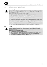
Page 68: ...ngine and remove the ignition key Secure the tractor against accidental start up and against rolling Switch off the PTO and disengage it After repair maintenance cleaning work or technical modifications are complete mount all protective coverings and safety devices again properly Avoid skin contact with oils greases cleaning agents and solvents In the event of injuries or burns due to oils cleanin...

Page 69: ...Schmi erpl an 0 mod_1197361829026_78 docx 18495 2 1 11 3 Lubrication Chart Pos 24 39 8 BA Wartung Mähwerke EasyC ut AM Mähwerke Schmier pläne Schmi erplan EC R 320 1 58 mod_1296737835250_78 docx 553950 1 1 EC 345 0 Fig 42 Pos 26 BA Seitenumbruch 0 mod_1196175311226_0 docx 4165 11 1 ...

Page 70: ...and on the bearing rings of the guard tubes Pos 27 2 4 BA Einl agerung Alle Gel enkstellen einölen 70 mod_1305633347429_78 docx 638432 1 Oil all joint points Pos 27 2 5 BA Einl agerung Lackschäden ausbesser n blanke Stellen gründlich mit R ostschutzmittel konser vi eren 70 mod_1305630900253_78 docx 638320 1 1 Touch up damaged paint and preserve all uncoated areas thoroughly with rust protection ag...

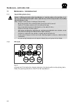
Page 71: ...isengage it After repair maintenance cleaning work or technical modifications are complete mount all protective coverings and safety devices again properly Avoid skin contact with oils greases cleaning agents and solvents In the event of injuries or burns due to oils cleaning agents or solvents contact a doctor immediately All other safety instructions must also be followed to avoid injuries and a...

Page 72: ...e certain they are tight or retighten them if necessary Check all electrical connection cables and the lighting Repair or replace if necessary Check the entire setting of the machine and correct if necessary Re read the operating instructions thoroughly Note Use vegetable oils and greases Pos 27 11 BA Ei nlag erung Rei bkupplung R eibkuppl ung l üften vor der Saison 3 mod_1204731645242_78 docx 727...

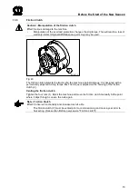
Page 73: ...4732297351_78 docx 72885 2 1 EC 257 0 1 2 Fig 43 The friction clutch protects the tractor and the machine against damage It is designed with a permanently adjusted turning torque MR The torque is applied on the housing of the friction clutch 2 Venting the friction clutch Tighten the four nuts 1 Block the machine and move the friction clutch manually to the point where it slips through Loosen the n...

Page 74: ...cure the tractor against accidental start up and against rolling Switch off the PTO and disengage it After repair maintenance cleaning work or technical modifications are complete mount all protective coverings and safety devices again properly Avoid skin contact with oils greases cleaning agents and solvents In the event of injuries or burns due to oils cleaning agents or solvents contact a docto...

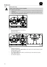
Page 75: ...ntil all machine parts have come to a complete stop When working under or on the raised machine the machine must be safely supported To save space the mowing unit can be lowered into transport position However the additional parking supports must be fitted to the mowing unit Pos 31 2 Überschriften Überschriften 3 U Z U mfang des Bei packs 39 mod_1268206369839_78 docx 358438 2 1 14 3 1 Scope of the...

Page 76: ...8 docx 358511 2 1 14 3 2 Attaching the parking supports Pos 31 7 Bei packs EasyCut Abstellstützen Bei pack 150 xxx xxx xx Anbau der Abstellstützen Bild 58 mod_1296742026637_78 docx 554064 2 1 a EC 348 0 II I III IV a 1 9 8 10 9 5 7 4 3 6 2 2 1 Fig 46 Pos 31 8 BA Seitenumbruch 0 mod_1196175311226_0 docx 4165 3 1 ...

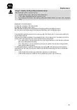
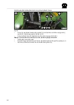
Page 77: ...g III at the appropriate places on the mowing unit Place the front parking support 1 on the screw points provided for it on the mowing unit and screw it on with screws 8 washers 9 and nuts 10 tighten nuts finger tight right and left side of the machine Push the rear parking supports 2 into the corresponding guides and secure them with the bolt Lowering the mowing unit Swivel the parking supports i...

Page 78: ... H ydraulische Feder entlastung U mfang des Bei packs Bild Feder entlastung 59 mod_1297666613133_78 docx 558640 3 1 EC 373 0 2 1 3 Fig 47 Pos 33 4 Bei packs EasyCut H ydraulische Feder entlastung Ei nzelteil e Tabelle Federentl astung 59 mod_1297666683987_78 docx 558666 1 Number Pos Part No Dimensions 1 4 00 900 244 0 M6 x 50 1 5 00 908 704 1 M6 1 6 00 909 906 0 SKM 6 1 7 00 910 411 1 6 4 12 5 x 1...

Page 79: ...9 Bei packs EasyCut H ydraulische Feder entlastung GEFAHR Einstell ung an den Entlastungsfedern 59 mod_1297665929816_78 docx 558525 2 1 DANGER Setting on the compensation springs Effect Danger to life or serious injuries Set the compensation springs only when the tension has been released adjusting lever a must be unlocked Compensation springs may be released only in the transport position or head...

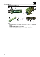
Page 80: ... docx 790221 3 1 Unscrew the Compensation Spring EC 405 a a d d b a c Fig 49 Remove the parts C out of the headstock and put down the compensation spring on the machine Remove the adjustment lever a and put it aside Remove the locking chain with cotter pin from the headstock and put it aside Pos 33 13 BA Seitenumbr uch 0 mod_1196175311226_0 docx 4165 1 ...

Page 81: ...lf a Install pre assembled cylinder 1 b in the rear hole using available pin Secure pin b with washer 9 and cotter pin 8 Screw pressure gauge 2 onto three point block Pos 33 15 Beipacks EasyC ut H ydr aulische Federentl astung Ohne C V Entlastungsfeder anschr auben 93 mod_1327494642919_78 docx 790277 1 Screw on the Compensation Spring EC 403 a Fig 51 Install the compensation spring a Pos 33 16 BA ...

Page 82: ...le locking block 3 onto the three point block using bolt 4 washer 7 detent edge washer 6 and nut 5 Screw hydraulic hose 90 degrees onto the pressure gauge connection Always counter with a 2nd wrench a on the pressure gauge connection Install upper hose clamp half Feed the longer hydraulic hose of the pre assembled cylinder through the opening c in the three point block and attach to the double loc...

Page 83: ...H Headland Position 38 Hydraulic spring compensation mechanism 78 Hydraulic system 15 Hydraulics 27 I Identification Plate 8 Identifying Symbols in the Operating Instructions 10 Inadmissible Modes of Operation 16 Information Required for Questions and Orders 8 Install the PTO shaft 30 Intended Use 9 Intermediate PTO shaft 30 Introduction 7 L Lubrication Chart 69 M Main gearbox 49 Maintenance 15 45...

Page 84: ...on to transport position 32 Swivelling parking support into transport position 31 37 T Technical data 9 Test run 71 Test run 45 Tightening Torques 46 Tightening Torques Countersunk Screws 47 U Unauthorised Conversion Modification and Spare Parts Production 16 W Working in the vicinity of power transmission lines 16 ...

Page 85: ......

Page 86: ...abrik Bernard Krone GmbH Heinrich Krone Straße 10 D 48480 Spelle Postfach 11 63 D 48478 Spelle Phone 49 0 59 77 935 0 Fax 49 0 59 77 935 339 Internet http www krone de eMail info ldm krone de konsequent kompetent ...

Reviews: